The Lens of Gravity: Einstein’s Rings

Einstein’s theory of gravity came from a simple happy thought that occurred to him as he imagined an unfortunate worker falling from a roof, losing hold of his hammer, only to find both the hammer and himself floating motionless relative to each other as if gravity had ceased to exist.  With this one thought, Einstein realized that the falling (i.e. accelerating) reference frame was in fact an inertial frame, and hence all the tricks that he had learned and invented to deal with inertial relativistic frames could apply just as well to accelerating frames in gravitational fields.

Gravitational lensing (and microlensing) have become a major tool of discovery in astrophysics applied to the study of quasars, dark matter and even the search for exoplanets.

Armed with this new perspective, one of the earliest discoveries that Einstein made was that gravity must bend light paths.  This phenomenon is fundamentally post-Newtonian, because there can be no possible force of gravity on a massless photon—yet Einstein’s argument for why gravity should bend light is so obvious that it is manifestly true, as demonstrated by Arthur Eddington during the solar eclipse of 1919, launching Einstein to world-wide fame. It is also demonstrated by the beautiful gravitational lensing phenomenon of Einstein arcs. Einstein arcs are the distorted images of bright distant light sources in the universe caused by an intervening massive object, like a galaxy or galaxy cluster, that bends the light rays. A number of these arcs are seen in images of the Abel cluster of galaxies in Fig. 1.

Fig. 1 Numerous Einstein arcs seen in the Abel cluster of galaxies.

Gravitational lensing (and microlensing) have become a major tool of discovery in astrophysics applied to the study of quasars, dark matter and even the search for exoplanets.  However, as soon as Einstein conceived of gravitational lensing, in 1912, he abandoned the idea as too small and too unlikely to ever be useful, much like he abandoned the idea of gravitational waves in 1915 as similarly being too small ever to detect.  It was only at the persistence of an amateur Czech scientist twenty years later that Einstein reluctantly agreed to publish his calculations on gravitational lensing.

The History of Gravitational Lensing

In 1912, only a few years after his “happy thought”, and fully three years before he published his definitive work on General Relativity, Einstein derived how light would be affected by a massive object, causing light from a distant source to be deflected like a lens. The historian of physics, Jürgen Renn discovered these derivations in Einstein’s notebooks while at the Max Planck Institute for the History of Science in Berlin in 1996 [1]. However, Einstein also calculated the magnitude of the effect and dismissed it as too small, and so he never published it.

Years later, in 1936, Einstein received a visit from a Czech electrical engineer Rudi Mandl, an amateur scientist who had actually obtained a small stipend from the Czech government to visit Einstein at the Institute for Advanced Study at Princeton. Mandl had conceived of the possibility of gravitational lensing and wished to bring it to Einstein’s attention, thinking that the master would certainly know what to do with the idea. Einstein was obliging, redoing his calculations of 1912 and obtaining once again the results that made him believe that the effect would be too small to be seen. However, Mandl was persistent and pressed Einstein to publish the results, which he did [2]. In his submission letter to the editor of Science, Einstein stated “Let me also thank you for your cooperation with the little publication, which Mister Mandl squeezed out of me. It is of little value, but it makes the poor guy happy”. Einstein’s pessimism was based on his thinking that isolated stars would be the only source of the gravitational lens (he did not “believe” in black holes), but in 1937 Fritz Zwicky at Cal Tech (a gadfly genius) suggested that the newly discovered phenomenon of “galaxy clusters” might provide the massive gravity that would be required to produce the effect. Although, to be visible, a distant source would need to be extremely bright.

Potential sources were discovered in the 1960’s using radio telescopes that discovered quasi-stellar objects (known as quasars) that are extremely bright and extremely far away. Quasars also appear in the visible range, and in 1979 a twin quasar was discovered by astronomers using the telescope at the Kitt Peak Obversvatory in Arizona–two quasars very close together that shared identical spectral fingerprints. The astronomers realized that it could be a twin image of a single quasar caused by gravitational lensing, which they published as a likely explanation. Although the finding was originally controversial, the twin-image was later confirmed, and many additional examples of gravitational lensing have since been discovered.

The Optics of Gravity and Light

Gravitational lenses are terrible optical instruments.  A good imaging lens has two chief properties: 1) It produces increasing delay on a wavefront as the radial distance from the optic axis decreases; and 2) it deflects rays with increasing deflection angle as the radial distance of a ray increases away from the optic axis (the center of the lens).  Both properties are part of the same effect: the conversion, by a lens, of an incident plane wave into a converging spherical wave.  A third property of a good lens ensures minimal aberrations of the converging wave: a quadratic dependence of wavefront delay on radial distance from the optic axis.  For instance, a parabolic lens produces a diffraction-limited focal spot.

Now consider the optical effects of gravity around a black hole.  One of Einstein’s chief discoveries during his early investigations into the effects of gravity on light is the analogy of warped space-time as having an effective refractive index.  Light propagates through space affected by gravity as if there were a refractive index associated with the gravitational potential.  In a previous blog on the optics of gravity, I showed the simple derivation of the refractive effects of gravity on light based on the Schwarschild metric applied to a null geodesic of a light ray.  The effective refractive index near a black hole is

This effective refractive index diverges at the Schwarzschild radius of the black hole. It produces the maximum delay, not on the optic axis as for a good lens, but at the finite distance RS.  Furthermore, the maximum deflection also occurs at RS, and the deflection decreases with increasing radial distance.  Both of these properties of gravitational lensing are opposite to the properties of a good lens.  For this reason, the phrase “gravitational lensing” is a bit of a misnomer.  Gravitating bodies certainly deflect light rays, but the resulting optical behavior is far from that of an imaging lens.

The path of a ray from a distant quasar, through the thin gravitational lens of a galaxy, and intersecting the location of the Earth, is shown in Fig. 2. The location of the quasar is a distance R from the “optic axis”. The un-deflected angular position is θ0, and with the intervening galaxy the image appears at the angular position θ. The angular magnification is therefore M = θ/θ0.

Fig. 2 Optical ray layout for gravitational lensing and Einstein rings. All angles are greatly exaggerated; typical angles are in the range of several arcseconds.

The deflection angles are related through

where b is the “impact parameter”

These two equations are solved to give to an expression that relates the unmagnified angle θ0 to the magnified angle θ as

where

is the angular size of the Einstein ring when the source is on the optic axis. The quadratic equation has two solutions that gives two images of the distant quasar. This is the origin of the “double image” that led to the first discovery of gravitational lensing in 1979.

When the distant quasar is on the optic axis, then θ0 = 0 and the deflection of the rays produces, not a double image, but an Einstein ring with an angular size of θE. For typical lensing objects, the angular size of Einstein rings are typically in the range of tens of microradians. The angular magnification for decreasing distance R diverges as

But this divergence is more a statement of the bad lens behavior than of actual image size. Because the gravitational lens is inverted (with greater deflection closer to the optic axis) compared to an ideal thin lens, it produces a virtual image ring that is closer than the original object, as in Fig. 3.

Fig. 3 Gravitational lensing does not produce an “image” but rather an Einstein ring that is virtual and magnified (appears closer).

The location of the virtual image behind the gravitational lens (when the quasar is on the optic axis) is obtained from

If the quasar is much further from the lens than the Earth, then the image location is zi = -L1, or behind the lens by the same distance from the Earth to the lens. The longitudinal magnification is then

Note that while the transverse (angular) magnification diverges as the object approaches the optic axis, the longitudinal magnification remains finite but always greater than unity.

The Caustic Curves of Einstein Rings

Because gravitational lenses have such severe aberration relative to an ideal lens, and because the angles are so small, an alternate approach to understanding the optics of gravity is through the theory of light caustics. In my previous blog on the optics of caustics, I described how sets of deflected rays of light become enclosed in envelopes that produce regions of high and low intensity. These envelopes are called caustics. Gravitational light deflection also causes caustics.

In addition to envelopes, it is also possible to trace the time delays caused by gravity on wavefronts. In the regions of the caustic envelopes, these wavefronts can fold back onto themselves so that different parts of the image arrive at different times coming from different directions.

An example of gravitational caustics is shown in Fig. 4. Rays are incident vertically on a gravitational thin lens which deflects the rays so that they overlap in the region below the lens. The red curves are selected wavefronts at three successively later times. The gravitational potential causes a time delay on the propgating front, with greater delays in regions of stronger gravitational potential. The envelope function that is tangent to the rays is called the caustic, here shown as the dense blue mesh. In this case there is a cusp in the caustic near z = -1 below the lens. The wavefronts become multiple-valued past the cusp

Fig. 4 Wavefronts (in red) perpendicular to the rays (in blue) from gravitational deflection of light. A cusp in the wavefront forms at the apex of the caustic ray envelope near z = -1. Farther from the lens the wavefront becomes double-valued, leading to different time delays for the two images if the object is off the optic axis. (All angle are greatly exaggerated.)

The intensity of the distant object past the lens is concentrated near the caustic envelope. The intensity of the caustic at z = -6 is shown in Fig. 5. The ring structure is the cross-sectional spatial intensity at the fixed observation plane, but a transform to the an angular image is one-to-one, so the caustic intensity distribution is also similar to the view of the Einstein ring from a position at z = -6 on the optic axis.

Fig. 5 Simulated caustic of an Einstein arc. This is the cross-sectional intensity at z = -6 from Fig. 4.

The gravitational potential is a function of the mass distribution in the gravitational lens. A different distribution with a flatter distribution of mass near the optic axis is shown in Fig. 6. There are multiple caustics in this case with multi-valued wavefronts. Because caustics are sensitive to mass distribution in the gravitational lens, astronomical observations of gravitational caustics can be used to back out the mass distribution, including dark matter or even distant exoplanets.

Fig. 6 Wavefronts and caustic for a much flatter mass distribution in the galaxy. The wavefront has multiple cusps in this case and the caustic has a double ring. The details of the caustics caused by the gravitational lens can provide insight into the mass distribution of the lensing object.

By David D. Nolte, April 5, 2021

Python Code gravfront.py

(Python code on GitHub.)

#!/usr/bin/env python3
# -*- coding: utf-8 -*-
"""
Created on Tue Mar 30 19:47:31 2021

gravfront.py

@author: David Nolte
Introduction to Modern Dynamics, 2nd edition (Oxford University Press, 2019)

Gravitational Lensing
"""

import numpy as np
from matplotlib import pyplot as plt

plt.close('all')

def refindex(x):
    n = n0/(1 + abs(x)**expon)**(1/expon);
    return n


delt = 0.001
Ly = 10
Lx = 5
n0 = 1
expon = 2   # adjust this from 1 to 10


delx = 0.01
rng = np.int(Lx/delx)
x = delx*np.linspace(-rng,rng)

n = refindex(x)

dndx = np.diff(n)/np.diff(x)

plt.figure(1)
lines = plt.plot(x,n)

plt.figure(2)
lines2 = plt.plot(dndx)

plt.figure(3)
plt.xlim(-Lx, Lx)
plt.ylim(-Ly, 2)
Nloop = 160;
xd = np.zeros((Nloop,3))
yd = np.zeros((Nloop,3))
for loop in range(0,Nloop):
    xp = -Lx + 2*Lx*(loop/Nloop)
    plt.plot([xp, xp],[2, 0],'b',linewidth = 0.25)

    thet = (refindex(xp+delt) - refindex(xp-delt))/(2*delt)
    xb = xp + np.tan(thet)*Ly
    plt.plot([xp, xb],[0, -Ly],'b',linewidth = 0.25)
    
    for sloop in range(0,3):
        delay = n0/(1 + abs(xp)**expon)**(1/expon) - n0
        dis = 0.75*(sloop+1)**2 - delay
        xfront = xp + np.sin(thet)*dis
        yfront = -dis*np.cos(thet)
                
        xd[loop,sloop] = xfront
        yd[loop,sloop] = yfront
        
for sloop in range(0,3):
    plt.plot(xd[:,sloop],yd[:,sloop],'r',linewidth = 0.5)

References

[1] J. Renn, T. Sauer and J. Stachel, “The Origin of Gravitational Lensing: A Postscript to Einstein’s 1936 Science Paper, Science 275. 184 (1997)

[2] A. Einstein, “Lens-Like Action of a Star by the Deviation of Light in the Gravitational Field”, Science 84, 506 (1936)

[3] (Here is an excellent review article on the topic.) J. Wambsganss, “Gravitational lensing as a powerful astrophysical tool: Multiple quasars, giant arcs and extrasolar planets,” Annalen Der Physik, vol. 15, no. 1-2, pp. 43-59, Jan-Feb (2006) SpringerLink


New from Oxford Press: Interference (2023)

Read the stories of the scientists and engineers who tamed light and used it to probe the universe.
Order Today from Amazon.

Order Today from Oxford U Press

Order Today from Barnes & Nobles

Caustic Curves and the Optics of Rays

Snorkeling above a shallow reef on a clear sunny day transports you to an otherworldly galaxy of spectacular deep colors and light reverberating off of the rippled surface.  Playing across the underwater floor of the reef is a fabulous light show of bright filaments entwining and fluttering, creating random mesh networks of light and dark.  These same patterns appear on the bottom of swimming pools in summer and in deep fountains in parks.

Johann Bernoulli had a stormy career and a problematic personality–but he was brilliant even among the bountiful Bernoulli clan. Using methods of tangents, he found the analytic solution of the caustic of the circle.

Something similar happens when a bare overhead light reflects from the sides of a circular glass of water.  The pattern no longer moves, but a dazzling filament splays across the bottom of the glass with a sharp bright cusp at the center. These bright filaments of light have an age old name — Caustics — meaning burning as in burning with light. The study of caustics goes back to Archimedes of Syracuse and his apocryphal burning mirrors that are supposed to have torched the invading triremes of the Roman navy in 212 BC.

Fig. 1 (left) Archimedes supposedly burning the Roman navy with caustics formed by a “burning mirror”. A wall painting from the Uffizi Gallery, Stanzino delle Matematiche, in Florence, Italy. Painted in 1600 by Gieulio Parigi. (right) The Mojave thermal farm uses 3000 acres of mirrors to actually do the trick.

Caustics in optics are concentrations of light rays that form bright filaments, often with cusp singularities. Mathematically, they are envelope curves that are tangent to a set of lines. Cata-caustics are caustics caused by light reflecting from curved surfaces. Dia-caustics are caustics caused by light refracting from transparent curved materials.

From Leonardo to Huygens

Even after Archimedes, burning mirrors remained an interest for a broad range of scientists, artists and engineers. Leonardo Da Vinci took an interest around 1503 – 1506 when he drew reflected caustics from a circular mirror in his many notebooks.

Fig. 2 Drawings of caustics of the circle in Leonardo Da Vinci’s notebooks circa 1503 – 1506. Digitized by the British Museum.

Almost two centuries later, Christian Huygens constructed the caustic of a circle in his Treatise on light : in which are explained the causes of that which occurs in reflection, & in refraction and particularly in the strange refraction of Iceland crystal. This is the famous treatise in which he explained his principle for light propagation as wavefronts. He was able to construct the caustic geometrically, but did not arrive at a functional form. He mentions that it has a cusp like a cycloid, but without being a cycloid. He first presented this work at the Paris Academy in 1678 where the news of his lecture went as far as Italy where a young German mathematician was traveling.

Fig. 3 Christian Huygens construction of the cusp of the caustic of the circle from his Treatise on Light (1690).

The Cata-caustics of Tschirnhaus and Bernoulli

In the decades after Newton and Leibniz invented the calculus, a small cadre of mathematicians strove to apply the new method to understand aspects of the physical world. At at a time when Newton had left the calculus behind to follow more arcane pursuits, Lebniz, Jakob and Johann Bernoulli, Guillaume de l’Hôpital, Émilie du Chatelet and Walter von Tschirnhaus were pushing notation reform (mainly following Leibniz) to make the calculus easier to learn and use, as well as finding new applications of which there were many.

Ehrenfried Walter von Tschirnhaus (1651 – 1708) was a German mathematician and physician and a lifelong friend of Leibniz, who he met in Paris in 1675. He was one of only five mathematicians to provide a solution to Johann Bernoulli’s brachistochrone problem. One of the recurring interests of von Tschirnhaus, that he revisited throughout his carrier, was in burning glasses and mirrors. A burning glass is a high-quality magnifying lens that brings the focus of the sun to a fine point to burn or anneal various items. Burning glasses were used to heat small items for manufacture or for experimentation. For instance, Priestly and Lavoisier routinely used burning glasses in their chemistry experiments. Low optical aberrations were required for the lenses to bring the light to the finest possible focus, so the study of optical focusing was an important topic both academically and practically. Tshirnhaus had his own laboratory to build and test burning mirrors, and he became aware of the cata-caustic patterns of light reflected from a circular mirror or glass surface. Given his parallel interest in the developing calculus methods, he published a paper in Acta Eruditorum in 1682 that constructed the envelope function created by the cata-caustics of a circle. However, Tschirnhaus did not produce the analytic function–that was provided by Johann Bernoulli ten years later in 1692.

Fig. 4 Excerpt from Acta Eruditorum 1682 by von Tschirnhaus.

Johann Bernoulli had a stormy career and a problematic personality–but he was brilliant even among the Bountiful Bernoulli clan. Using methods of tangents, he found the analytic solution of the caustic of the circle. He did this by stating the general equation for all reflected rays and then finding when their y values are independent of changing angle … in other words using the principle of stationarity which would later become a potent tool in the hands of Lagrange as he developed Lagrangian physics.

Fig. 5 Bernoulli’s construction of the equations of rays reflected by the unit circle.

The equation for the reflected ray, expressing y as a function of x for a given angle α in Fig. 5, is

The condition of the caustic envelope requires the change in y with respect to the angle α to vanish while treating x as a constant. This is a partial derivative, and Johann Bernoulli is giving an early use of this method in 1692 to ensure the stationarity of y with respect to the changing angle. The partial derivative is

This is solved to give

Plugging this into the equation at the top equation above yields

These last two expressions for x and y in terms of the angle α are a parametric representation of the caustic. Combining them gives the solution to the caustic of the circle

The square root provides the characteristic cusp at the center of the caustic.

Fig. 6 Caustic of a circle. Image was generated using the Python program raycaustic.py.

Python Code: raycaustic.py

There are lots of options here. Try them all … then add your own!

#!/usr/bin/env python3
# -*- coding: utf-8 -*-
"""
Created on Tue Feb 16 16:44:42 2021

raycaustic.py

@author: nolte

D. D. Nolte, Optical Interferometry for Biology and Medicine (Springer,2011)
"""

import numpy as np
from matplotlib import pyplot as plt

plt.close('all')

# model_case 1 = cosine
# model_case 2 = circle
# model_case 3 = square root
# model_case 4 = inverse power law
# model_case 5 = ellipse
# model_case 6 = secant
# model_case 7 = parabola
# model_case 8 = Cauchy

model_case = int(input('Input Model Case (1-7)'))
if model_case == 1:
    model_title = 'cosine'
    xleft = -np.pi
    xright = np.pi
    ybottom = -1
    ytop = 1.2

elif model_case == 2:
    model_title = 'circle'
    xleft = -1
    xright = 1
    ybottom = -1
    ytop = .2

elif model_case == 3:
    model_title = 'square-root'
    xleft = 0
    xright = 4
    ybottom = -2
    ytop = 2

elif model_case == 4:
    model_title = 'Inverse Power Law'
    xleft = 1e-6
    xright = 4
    ybottom = 0
    ytop = 4
    
elif model_case == 5:
    model_title = 'ellipse'
    a = 0.5
    b = 2
    xleft = -b
    xright = b
    ybottom = -a
    ytop = 0.5*b**2/a
    
elif model_case == 6:
    model_title = 'secant'
    xleft = -np.pi/2
    xright = np.pi/2
    ybottom = 0.5
    ytop = 4
    
elif model_case == 7:
    model_title = 'Parabola'
    xleft = -2
    xright = 2
    ybottom = 0
    ytop = 4

elif model_case == 8:
    model_title = 'Cauchy'
    xleft = 0
    xright = 4
    ybottom = 0
    ytop = 4
    
def feval(x):

    if model_case == 1:
        y = -np.cos(x)

    elif model_case == 2:
        y = -np.sqrt(1-x**2)

    elif model_case == 3:
        y = -np.sqrt(x)
        
    elif model_case == 4:
        y = x**(-0.75)
        
    elif model_case == 5:
        y = -a*np.sqrt(1-x**2/b**2)

    elif model_case == 6:
        y = 1.0/np.cos(x)

    elif model_case == 7:
        y = 0.5*x**2  
        
    elif model_case == 8:
        y = 1/(1 + x**2)

    return y

xx = np.arange(xleft,xright,0.01)
yy = feval(xx)

lines = plt.plot(xx,yy)
plt.xlim(xleft, xright)
plt.ylim(ybottom, ytop)

delx = 0.001
N = 75

for i in range(N+1):
    
    x = xleft + (xright-xleft)*(i-1)/N
    
    val = feval(x)
    valp = feval(x+delx/2)
    valm = feval(x-delx/2)
    deriv = (valp-valm)/delx
    
    phi = np.arctan(deriv)
    slope =  np.tan(np.pi/2 + 2*phi)

    if np.abs(deriv) < 1:
        xf = (ytop-val+slope*x)/slope;
        yf = ytop;
    else:
        xf = (ybottom-val+slope*x)/slope;
        yf = ybottom;
    plt.plot([x, x],[ytop, val],linewidth = 0.5)       
    plt.plot([x, xf],[val, yf],linewidth = 0.5)
    plt.gca().set_aspect('equal', adjustable='box')       
    plt.show()
    

The Dia-caustics of Swimming Pools

A caustic is understood mathematically as the envelope function of multiple rays that converge in the Fourier domain (angular deflection measured at far distances).  These are points of mathematical stationarity, in which the ray density is invariant to first order in deviations in the refracting surface.  The rays themselves are the trajectories of the Eikonal Equation as rays of light thread their way through complicated optical systems.

The basic geometry is shown in Fig 7 for a ray incident on a nonplanar surface emerging into a less-dense medium.  From Snell’s law we have the relation for light entering a dense medium like light into water

where n is the relative index (ratio), and the small-angle approximation has been made.  The incident angle θ1 is simply related to the slope of the interface dh/dx as

where the small-angle approximation is used again.  The angular deflection relative to the optic axis is then

which is equal to the optical path difference through the sample.

Fig. 7 The geometry of ray deflection by a random surface. Reprinted from Optical Interferometry, Ref. [1].

In two dimensions, the optical path difference can be replaced with a general potential

and the two orthogonal angular deflections (measured in the far field on a Fourier plane) are

These angles describe the deflection of the rays across the sample surface. They are also the right-hand side of the Eikonal Equation, the equation governing ray trajectories through optical systems.

Caustics are lines of stationarity, meaning that the density of rays is independent of first-order changes in the refracting sample.  The condition of stationarity is defined by the Jacobian of the transformation from (x,y) to (θx, θy) with

where the second expression is the Hessian determinant of the refractive power of the uneven surface. When this condition is satisfied, the envelope function bounding groups of collected rays is stationary to perturbations in the inhomogeneous sample.

An example of diacaustic formation from a random surface is shown in Fig. 8 generated by the Python program caustic.py. The Jacobian density (center) outlines regions in which the ray density is independent of small changes in the surface. They are positions of the zeros of the Hessian determinant, the regions of zero curvature of the surface or potential function. These high-intensity regions spread out and are intercepted at some distance by a suface, like the bottom of a swimming pool, where the concentrated rays create bright filaments. As the wavelets on the surface of the swimming pool move, the caustic filaments on the bottom of the swimming pool dance about.

Optical caustics also occur in the gravitational lensing of distant quasars by galaxy clusters in the formation of Einstein rings and arcs seen by deep field telescopes, as described in my following blog post.

Fig. 8 Formation of diacaustics by transmission through a transparent material of random thickness (left). The Jacobian density is shown at the center. These are regions of constant ray density. A near surface displays caustics (right) as on the bottom of a swimming pool. Images were generated using the Python program caustic.py.

Python Code: caustic.py

This Python code was used to generate the caustic patterns in Fig. 8. You can change the surface roughness by changing the divisors on the last two arguments on Line 58. The distance to the bottom of the swimming pool can be changed by changing the parameter d on Line 84.

#!/usr/bin/env python3
# -*- coding: utf-8 -*-
"""
Created on Tue Feb 16 19:50:54 2021

caustic.py

@author: nolte

D. D. Nolte, Optical Interferometry for Biology and Medicine (Springer,2011)
"""

import numpy as np
from matplotlib import pyplot as plt
from numpy import random as rnd
from scipy import signal as signal

plt.close('all')

N = 256

def gauss2(sy,sx,wy,wx):
    
    x = np.arange(-sx/2,sy/2,1)
    y = np.arange(-sy/2,sy/2,1)
    y = y[..., None]
    
    ex = np.ones(shape=(sy,1))
    x2 = np.kron(ex,x**2/(2*wx**2));
    
    ey = np.ones(shape=(1,sx));
    y2 = np.kron(y**2/(2*wy**2),ey);

    rad2 = (x2+y2);

    A = np.exp(-rad2);

    return A

def speckle2(sy,sx,wy,wx):

    Btemp = 2*np.pi*rnd.rand(sy,sx);
    B = np.exp(complex(0,1)*Btemp);

    C = gauss2(sy,sx,wy,wx);

    Atemp = signal.convolve2d(B,C,'same');

    Intens = np.mean(np.mean(np.abs(Atemp)**2));

    D = np.real(Atemp/np.sqrt(Intens));

    Dphs = np.arctan2(np.imag(D),np.real(D));

    return D, Dphs


Sp, Sphs = speckle2(N,N,N/16,N/16)

plt.figure(2)
plt.matshow(Sp,2,cmap=plt.cm.get_cmap('seismic'))  # hsv, seismic, bwr
plt.show()

fx, fy = np.gradient(Sp);

fxx,fxy = np.gradient(fx);
fyx,fyy = np.gradient(fy);

J = fxx*fyy - fxy*fyx;

D = np.abs(1/J)

plt.figure(3)
plt.matshow(D,3,cmap=plt.cm.get_cmap('gray'))  # hsv, seismic, bwr
plt.clim(0,0.5e7)
plt.show()

eps = 1e-7
cnt = 0
E = np.zeros(shape=(N,N))
for yloop in range(0,N-1):
    for xloop in range(0,N-1):
        
        d = N/2
        
        indx = int(N/2 + (d*(fx[yloop,xloop])+(xloop-N/2)/2))
        indy = int(N/2 + (d*(fy[yloop,xloop])+(yloop-N/2)/2))
        
        if ((indx > 0) and (indx < N)) and ((indy > 0) and (indy < N)):
            E[indy,indx] = E[indy,indx] + 1

plt.figure(4)
plt.imshow(E,interpolation='bicubic',cmap=plt.cm.get_cmap('gray'))
plt.clim(0,30)
plt.xlim(N/4, 3*N/4)
plt.ylim(N/4,3*N/4)

By David D. Nolte, Feb. 28, 2021


External Link: Youtube Video


Read more from Oxford University Press: Interference (2023)

The stories of the scientists and engineers who tamed light and used it to probe the universe.

Available at Oxford U Press

Available at Amazon.

Available at Barnes & Nobles


References

[1] D. D. Nolte, “Speckle and Spatial Coherence,” Chapter 3 in Optical Interferometry for Biology and Medicine (Springer, 2012), pp. 95-121.

[2] E. Hairer and G. Wanner, Analysis by its history. (Springer, 1996)

[3] C. Huygens (1690), Treatise on light : in which are explained the causes of that which occurs in reflection, & in refraction and particularly in the strange refraction of Iceland crystal. Ed. S. P. Thompson, (University of Chicago Press, 1950).

Orbiting Photons around a Black Hole

The physics of a path of light passing a gravitating body is one of the hardest concepts to understand in General Relativity, but it is also one of the easiest.  It is hard because there can be no force of gravity on light even though the path of a photon bends as it passes a gravitating body.  It is easy, because the photon is following the simplest possible path—a geodesic equation for force-free motion.

         This blog picks up where my last blog left off, having there defined the geodesic equation and presenting the Schwarzschild metric.  With those two equations in hand, we could simply solve for the null geodesics (a null geodesic is the path of a light beam through a manifold).  But there turns out to be a simpler approach that Einstein came up with himself (he never did like doing things the hard way).  He just had to sacrifice the fundamental postulate that he used to explain everything about Special Relativity.

Throwing Special Relativity Under the Bus

The fundamental postulate of Special Relativity states that the speed of light is the same for all observers.  Einstein posed this postulate, then used it to derive some of the most astonishing consequences of Special Relativity—like E = mc2.  This postulate is at the rock core of his theory of relativity and can be viewed as one of the simplest “truths” of our reality—or at least of our spacetime. 

            Yet as soon as Einstein began thinking how to extend SR to a more general situation, he realized almost immediately that he would have to throw this postulate out.   While the speed of light measured locally is always equal to c, the apparent speed of light observed by a distant observer (far from the gravitating body) is modified by gravitational time dilation and length contraction.  This means that the apparent speed of light, as observed at a distance, varies as a function of position.  From this simple conclusion Einstein derived a first estimate of the deflection of light by the Sun, though he initially was off by a factor of 2.  (The full story of Einstein’s derivation of the deflection of light by the Sun and the confirmation by Eddington is in Chapter 7 of Galileo Unbound (Oxford University Press, 2018).)

The “Optics” of Gravity

The invariant element for a light path moving radially in the Schwarzschild geometry is

The apparent speed of light is then

where c(r) is  always less than c, when observing it from flat space.  The “refractive index” of space is defined, as for any optical material, as the ratio of the constant speed divided by the observed speed

Because the Schwarzschild metric has the property

the effective refractive index of warped space-time is

with a divergence at the Schwarzschild radius.

            The refractive index of warped space-time in the limit of weak gravity can be used in the ray equation (also known as the Eikonal equation described in an earlier blog)

where the gradient of the refractive index of space is

The ray equation is then a four-variable flow

These equations represent a 4-dimensional flow for a light ray confined to a plane.  The trajectory of any light path is found by using an ODE solver subject to the initial conditions for the direction of the light ray.  This is simple for us to do today with Python or Matlab, but it was also that could be done long before the advent of computers by early theorists of relativity like Max von Laue  (1879 – 1960).

The Relativity of Max von Laue

In the Fall of 1905 in Berlin, a young German physicist by the name of Max Laue was sitting in the physics colloquium at the University listening to another Max, his doctoral supervisor Max Planck, deliver a seminar on Einstein’s new theory of relativity.  Laue was struck by the simplicity of the theory, in this sense “simplistic” and hence hard to believe, but the beauty of the theory stuck with him, and he began to think through the consequences for experiments like the Fizeau experiment on partial ether drag.

         Armand Hippolyte Louis Fizeau (1819 – 1896) in 1851 built one of the world’s first optical interferometers and used it to measure the speed of light inside moving fluids.  At that time the speed of light was believed to be a property of the luminiferous ether, and there were several opposing theories on how light would travel inside moving matter.  One theory would have the ether fully stationary, unaffected by moving matter, and hence the speed of light would be unaffected by motion.  An opposite theory would have the ether fully entrained by matter and hence the speed of light in moving matter would be a simple sum of speeds.  A middle theory considered that only part of the ether was dragged along with the moving matter.  This was Fresnel’s partial ether drag hypothesis that he had arrived at to explain why his friend Francois Arago had not observed any contribution to stellar aberration from the motion of the Earth through the ether.  When Fizeau performed his experiment, the results agreed closely with Fresnel’s drag coefficient, which seemed to settle the matter.  Yet when Michelson and Morley performed their experiments of 1887, there was no evidence for partial drag.

         Even after the exposition by Einstein on relativity in 1905, the disagreement of the Michelson-Morley results with Fizeau’s results was not fully reconciled until Laue showed in 1907 that the velocity addition theorem of relativity gave complete agreement with the Fizeau experiment.  The velocity observed in the lab frame is found using the velocity addition theorem of special relativity. For the Fizeau experiment, water with a refractive index of n is moving with a speed v and hence the speed in the lab frame is

The difference in the speed of light between the stationary and the moving water is the difference

where the last term is precisely the Fresnel drag coefficient.  This was one of the first definitive “proofs” of the validity of Einstein’s theory of relativity, and it made Laue one of relativity’s staunchest proponents.  Spurred on by his success with the Fresnel drag coefficient explanation, Laue wrote the first monograph on relativity theory, publishing it in 1910. 

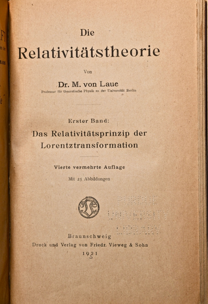
Fig. 1 Front page of von Laue’s textbook, first published in 1910, on Special Relativity (this is a 4-th edition published in 1921).

A Nobel Prize for Crystal X-ray Diffraction

In 1909 Laue became a Privatdozent under Arnold Sommerfeld (1868 – 1951) at the university in Munich.  In the Spring of 1912 he was walking in the Englischer Garten on the northern edge of the city talking with Paul Ewald (1888 – 1985) who was finishing his doctorate with Sommerfed studying the structure of crystals.  Ewald was considering the interaction of optical wavelength with the periodic lattice when it struck Laue that x-rays would have the kind of short wavelengths that would allow the crystal to act as a diffraction grating to produce multiple diffraction orders.  Within a few weeks of that discussion, two of Sommerfeld’s students (Friedrich and Knipping) used an x-ray source and photographic film to look for the predicted diffraction spots from a copper sulfate crystal.  When the film was developed, it showed a constellation of dark spots for each of the diffraction orders of the x-rays scattered from the multiple periodicities of the crystal lattice.  Two years later, in 1914, Laue was awarded the Nobel prize in physics for the discovery.  That same year his father was elevated to the hereditary nobility in the Prussian empire and Max Laue became Max von Laue.

            Von Laue was not one to take risks, and he remained conservative in many of his interests.  He was immensely respected and played important roles in the administration of German science, but his scientific contributions after receiving the Nobel Prize were only modest.  Yet as the Nazis came to power in the early 1930’s, he was one of the few physicists to stand up and resist the Nazi take-over of German physics.  He was especially disturbed by the plight of the Jewish physicists.  In 1933 he was invited to give the keynote address at the conference of the German Physical Society in Wurzburg where he spoke out against the Nazi rejection of relativity as they branded it “Jewish science”.  In his speech he likened Einstein, the target of much of the propaganda, to Galileo.  He said, “No matter how great the repression, the representative of science can stand erect in the triumphant certainty that is expressed in the simple phrase: And yet it moves.”  Von Laue believed that truth would hold out in the face of the proscription against relativity theory by the Nazi regime.  The quote “And yet it moves” is supposed to have been muttered by Galileo just after his abjuration before the Inquisition, referring to the Earth moving around the Sun.  Although the quote is famous, it is believed to be a myth.

            In an odd side-note of history, von Laue sent his gold Nobel prize medal to Denmark for its safe keeping with Niels Bohr so that it would not be paraded about by the Nazi regime.  Yet when the Nazis invaded Denmark, to avoid having the medals fall into the hands of the Nazis, the medal was dissolved in aqua regia by a member of Bohr’s team, George de Hevesy.  The gold completely dissolved into an orange liquid that was stored in a beaker high on a shelf through the war.  When Denmark was finally freed, the dissolved gold was precipitated out and a new medal was struck by the Nobel committee and re-presented to von Laue in a ceremony in 1951. 

The Orbits of Light Rays

Von Laue’s interests always stayed close to the properties of light and electromagnetic radiation ever since he was introduced to the field when he studied with Woldemor Voigt at Göttingen in 1899.  This interest included the theory of relativity, and only a few years after Einstein published his theory of General Relativity and Gravitation, von Laue added to his earlier textbook on relativity by writing a second volume on the general theory.  The new volume was published in 1920 and included the theory of the deflection of light by gravity. 

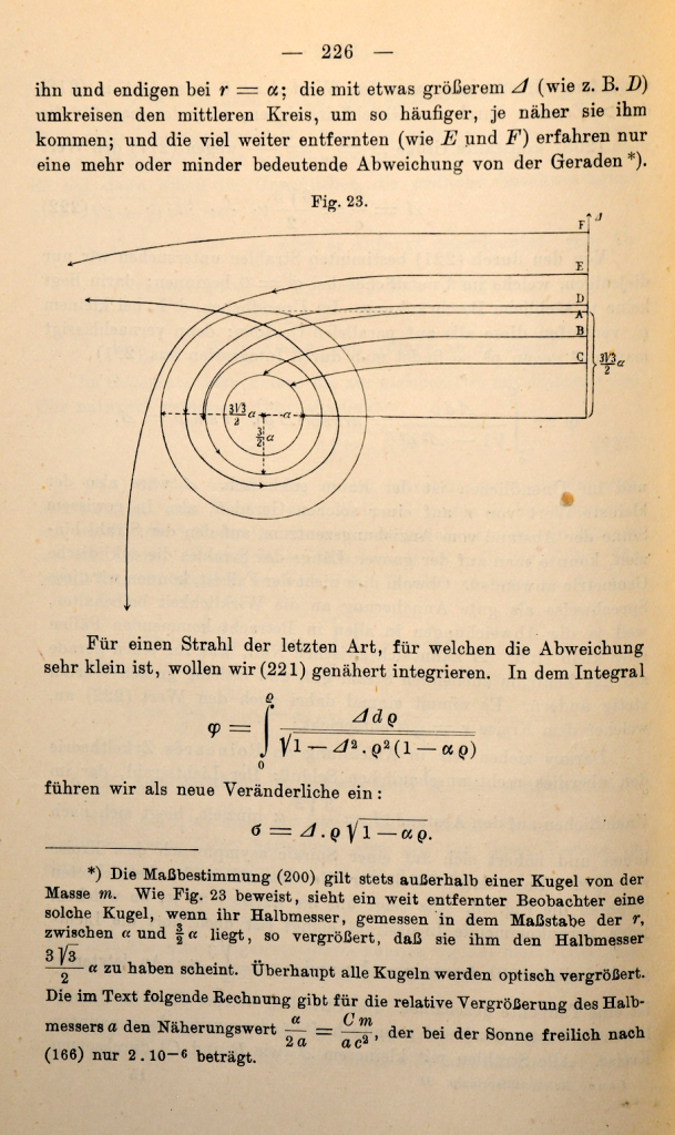
         One of the very few illustrations in his second volume is of light coming into interaction with a super massive gravitational field characterized by a Schwarzschild radius.  (No one at the time called it a “black hole”, nor even mentioned Schwarzschild.  That terminology came much later.)  He shows in the drawing, how light, if incident at just the right impact parameter, would actually loop around the object.  This is the first time such a diagram appeared in print, showing the trajectory of light so strongly affected by gravity.

Fig. 2 A page from von Laue’s second volume on relativity (first published in 1920) showing the orbit of a photon around a compact mass with “gravitational cutoff” (later known as a “black hole:”). The figure is drawn semi-quantitatively, but the phenomenon was clearly understood by von Laue.

Python Code: gravlens.py

#!/usr/bin/env python3
# -*- coding: utf-8 -*-
"""
gravlens.py
Created on Tue May 28 11:50:24 2019
@author: nolte
D. D. Nolte, Introduction to Modern Dynamics: Chaos, Networks, Space and Time, 2nd ed. (Oxford,2019)
"""

import numpy as np
import matplotlib as mpl
from mpl_toolkits.mplot3d import Axes3D
from scipy import integrate
from matplotlib import pyplot as plt
from matplotlib import cm
import time
import os

plt.close('all')

def create_circle():
	circle = plt.Circle((0,0), radius= 10, color = 'black')
	return circle

def show_shape(patch):
	ax=plt.gca()
	ax.add_patch(patch)
	plt.axis('scaled')
	plt.show()
    
def refindex(x,y):
    
    A = 10
    eps = 1e-6
    
    rp0 = np.sqrt(x**2 + y**2);
        
    n = 1/(1 - A/(rp0+eps))
    fac = np.abs((1-9*(A/rp0)**2/8))   # approx correction to Eikonal
    nx = -fac*n**2*A*x/(rp0+eps)**3
    ny = -fac*n**2*A*y/(rp0+eps)**3
     
    return [n,nx,ny]

def flow_deriv(x_y_z,tspan):
    x, y, z, w = x_y_z
    
    [n,nx,ny] = refindex(x,y)
        
    yp = np.zeros(shape=(4,))
    yp[0] = z/n
    yp[1] = w/n
    yp[2] = nx
    yp[3] = ny
    
    return yp
                
for loop in range(-5,30):
    
    xstart = -100
    ystart = -2.245 + 4*loop
    print(ystart)
    
    [n,nx,ny] = refindex(xstart,ystart)


    y0 = [xstart, ystart, n, 0]

    tspan = np.linspace(1,400,2000)

    y = integrate.odeint(flow_deriv, y0, tspan)

    xx = y[1:2000,0]
    yy = y[1:2000,1]


    plt.figure(1)
    lines = plt.plot(xx,yy)
    plt.setp(lines, linewidth=1)
    plt.show()
    plt.title('Photon Orbits')
    
c = create_circle()
show_shape(c)
axes = plt.gca()
axes.set_xlim([-100,100])
axes.set_ylim([-100,100])

# Now set up a circular photon orbit
xstart = 0
ystart = 15

[n,nx,ny] = refindex(xstart,ystart)

y0 = [xstart, ystart, n, 0]

tspan = np.linspace(1,94,1000)

y = integrate.odeint(flow_deriv, y0, tspan)

xx = y[1:1000,0]
yy = y[1:1000,1]

plt.figure(1)
lines = plt.plot(xx,yy)
plt.setp(lines, linewidth=2, color = 'black')
plt.show()

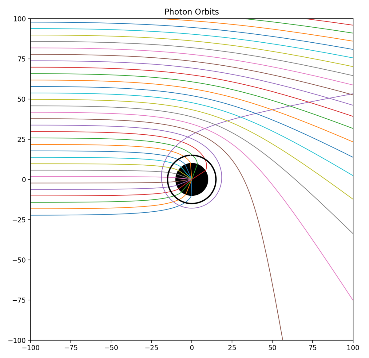
One of the most striking effects of gravity on photon trajectories is the possibility for a photon to orbit a black hole in a circular orbit. This is shown in Fig. 3 as the black circular ring for a photon at a radius equal to 1.5 times the Schwarzschild radius. This radius defines what is known as the photon sphere. However, the orbit is not stable. Slight deviations will send the photon spiraling outward or inward.

The Eikonal approximation does not strictly hold under strong gravity, but the Eikonal equations with the effective refractive index of space still yield semi-quantitative behavior. In the Python code, a correction factor is used to match the theory to the circular photon orbits, while still agreeing with trajectories far from the black hole. The results of the calculation are shown in Fig. 3. For large impact parameters, the rays are deflected through a finite angle. At a critical impact parameter, near 3 times the Schwarzschild radius, the ray loops around the black hole. For smaller impact parameters, the rays are captured by the black hole.

Fig. 3 Photon orbits near a black hole calculated using the Eikonal equation and the effective refractive index of warped space. One ray, near the critical impact parameter, loops around the black hole as predicted by von Laue. The central black circle is the black hole with a Schwarzschild radius of 10 units. The black ring is the circular photon orbit at a radius 1.5 times the Schwarzschild radius.

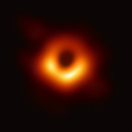
Photons pile up around the black hole at the photon sphere. The first image ever of the photon sphere of a black hole was made earlier this year (announced April 10, 2019). The image shows the shadow of the supermassive black hole in the center of Messier 87 (M87), an elliptical galaxy 55 million light-years from Earth. This black hole is 6.5 billion times the mass of the Sun. Imaging the photosphere required eight ground-based radio telescopes placed around the globe, operating together to form a single telescope with an optical aperture the size of our planet.  The resolution of such a large telescope would allow one to image a half-dollar coin on the surface of the Moon, although this telescope operates in the radio frequency range rather than the optical.

Fig. 4 Scientists have obtained the first image of a black hole, using Event Horizon Telescope observations of the center of the galaxy M87. The image shows a bright ring formed as light bends in the intense gravity around a black hole that is 6.5 billion times more massive than the Sun.

By David D. Nolte, July 29, 2019

Further Reading

Introduction to Modern Dynamics: Chaos, Networks, Space and Time, 2nd Ed. (Oxford University Press, 2019)

Interference: The History of Optical Interferometry and the Scientists who Tamed Light (Oxford University Press, 2023)

B. Lavenda, The Optical Properties of Gravity, J. Mod. Phys, 8 8-3-838 (2017)


New from Oxford University Press: Interference and the History of Light and Optics (2023)

The Iconic Eikonal and the Optical Path

Nature loves the path of steepest descent.  Place a ball on a smooth curved surface and release it, and it will instantansouly accelerate in the direction of steepest descent.  Shoot a laser beam from an oblique angle onto a piece of glass to hit a target inside, and the path taken by the beam is the only path that decreases the distance to the target in the shortest time.  Diffract a stream of electrons from the surface of a crystal, and quantum detection events are greatest at the positions where the troughs and peaks of the deBroglie waves converge the most.  The first example is Newton’s second law.  The second example is Fermat’s principle and Snell’s Law.  The third example is Feynman’s path-integral formulation of quantum mechanics.  They all share in common a minimization principle—the principle of least action—that the path of a dynamical system is the one that minimizes a property known as “action”.

The Eikonal Equation is the “F = ma” of ray optics.  It’s solutions describe the paths of light rays through complicated media.

         The principle of least action, first proposed by the French physicist Maupertuis through mechanical analogy, became a principle of Lagrangian mechanics in the hands of Lagrange, but was still restricted to mechanical systems of particles.  The principle was generalized forty years later by Hamilton, who began by considering the propagation of light waves, and ended by transforming mechanics into a study of pure geometry divorced from forces and inertia.  Optics played a key role in the development of mechanics, and mechanics returned the favor by giving optics the Eikonal Equation.  The Eikonal Equation is the “F = ma” of ray optics.  It’s solutions describe the paths of light rays through complicated media.

Malus’ Theorem

Anyone who has taken a course in optics knows that Étienne-Louis Malus (1775-1812) discovered the polarization of light, but little else is taught about this French mathematician who was one of the savants Napoleon had taken along with himself when he invaded Egypt in 1798.  After experiencing numerous horrors of war and plague, Malus returned to France damaged but wiser.  He discovered the polarization of light in the Fall of 1808 as he was playing with crystals of icelandic spar at sunset and happened to view last rays of the sun reflected from the windows of the Luxumbourg palace.  Icelandic spar produces double images in natural light because it is birefringent.  Malus discovered that he could extinguish one of the double images of the Luxumbourg windows by rotating the crystal a certain way, demonstrating that light is polarized by reflection.  The degree to which light is extinguished as a function of the angle of the polarizing crystal is known as Malus’ Law

Fronts-piece to the Description de l’Égypte , the first volume published by Joseph Fourier in 1808 based on the report of the savants of L’Institute de l’Égypte that included Monge, Fourier and Malus, among many other French scientists and engineers.

         Malus had picked up an interest in the general properties of light and imaging during lulls in his ordeal in Egypt.  (To read about Malus’ misadventures during Napoleon’s campaign in Egypt, see Chapter 1 of Interference.) He was an emissionist following his compatriot Laplace, rather than an undulationist following Thomas Young.  It is ironic that the French scientists were staunchly supporting Newton on the nature of light, while the British scientist Thomas Young was trying to upend Netwonian optics.  Almost all physicists at that time were emissionists, only a few years after Young’s double-slit experiment of 1804, and few serious scientists accepted Young’s theory of the wave nature of light until Fresnel and Arago supplied the rigorous theory and experimental proofs much later in 1819. 

Malus’ Theorem states that rays perpendicular to an initial surface are perpendicular to a later surface after reflection in an optical system. This theorem is the starting point for the Eikonal ray equation, as well as for modern applications in adaptive optics. This figure shows a propagating aberrated wavefront that is “compensated” by a deformable mirror to produce a tight focus.

         As a prelude to his later discovery of polarization, Malus had earlier proven a theorem about trajectories that particles of light take through an optical system.  One of the key questions about the particles of light in an optical system was how they formed images.  The physics of light particles moving through lenses was too complex to treat at that time, but reflection was relatively easy based on the simple reflection law.  Malus proved a theorem mathematically that after a reflection from a curved mirror, a set of rays perpendicular to an initial nonplanar surface would remain perpendicular at a later surface after reflection (this property is closely related to the conservation of optical etendue).  This is known as Malus’ Theorem, and he thought it only held true after a single reflection, but later mathematicians proved that it remains true even after an arbitrary number of reflections, even in cases when the rays intersect to form an optical effect known as a caustic.  The mathematics of caustics would catch the interest of an Irish mathematician and physicist who helped launch a new field of mathematical physics.

Etienne-Louis Malus

Hamilton’s Characteristic Function

William Rowan Hamilton (1805 – 1865) was a child prodigy who taught himself thirteen languages by the time he was thirteen years old (with the help of his linguist uncle), but mathematics became his primary focus at Trinity College at the University in Dublin.  His mathematical prowess was so great that he was made the Astronomer Royal of Ireland while still an undergraduate student.  He also became fascinated in the theory of envelopes of curves and in particular to the mathematics of caustic curves in optics. 

         In 1823 at the age of 18, he wrote a paper titled Caustics that was read to the Royal Irish Academy.  In this paper, Hamilton gave an exceedingly simple proof of Malus’ Law, but that was perhaps the simplest part of the paper.  Other aspects were mathematically obscure and reviewers requested further additions and refinements before publication.  Over the next four years, as Hamilton expanded this work on optics, he developed a new theory of optics, the first part of which was published as Theory of Systems of Rays in 1827 with two following supplements completed by 1833 but never published.

         Hamilton’s most important contribution to optical theory (and eventually to mechanics) he called his characteristic function.  By applying the principle of Fermat’s least time, which he called his principle of stationary action, he sought to find a single unique function that characterized every path through an optical system.  By first proving Malus’ Theorem and then applying the theorem to any system of rays using the principle of stationary action, he was able to construct two partial differential equations whose solution, if it could be found, defined every ray through the optical system.  This result was completely general and could be extended to include curved rays passing through inhomogeneous media.  Because it mapped input rays to output rays, it was the most general characterization of any defined optical system.  The characteristic function defined surfaces of constant action whose normal vectors were the rays of the optical system.  Today these surfaces of constant action are called the Eikonal function (but how it got its name is the next chapter of this story).  Using his characteristic function, Hamilton predicted a phenomenon known as conical refraction in 1832, which was subsequently observed, launching him to a level of fame unusual for an academic.

         Once Hamilton had established his principle of stationary action of curved light rays, it was an easy step to extend it to apply to mechanical systems of particles with curved trajectories.  This step produced his most famous work On a General Method in Dynamics published in two parts in 1834 and 1835 [1] in which he developed what became known as Hamiltonian dynamics.  As his mechanical work was extended by others including Jacobi, Darboux and Poincaré, Hamilton’s work on optics was overshadowed, overlooked and eventually lost.  It was rediscovered when Schrödinger, in his famous paper of 1926, invoked Hamilton’s optical work as a direct example of the wave-particle duality of quantum mechanics [2]. Yet in the interim, a German mathematician tackled the same optical problems that Hamilton had seventy years earlier, and gave the Eikonal Equation its name.

Bruns’ Eikonal

The German mathematician Heinrich Bruns (1848-1919) was engaged chiefly with the measurement of the Earth, or geodesy.  He was a professor of mathematics in Berlin and later Leipzig.  One claim fame was that one of his graduate students was Felix Hausdorff [3] who would go on to much greater fame in the field of set theory and measure theory (the Hausdorff dimension was a precursor to the fractal dimension).  Possibly motivated by his studies done with Hausdorff on refraction of light by the atmosphere, Bruns became interested in Malus’ Theorem for the same reasons and with the same goals as Hamilton, yet was unaware of Hamilton’s work in optics. 

         The mathematical process of creating “images”, in the sense of a mathematical mapping, made Bruns think of the Greek word  εικων which literally means “icon” or “image”, and he published a small book in 1895 with the title Das Eikonal in which he derived a general equation for the path of rays through an optical system.  His approach was heavily geometrical and is not easily recognized as an equation arising from variational principals.  It rediscovered most of the results of Hamilton’s paper on the Theory of Systems of Rays and was thus not groundbreaking in the sense of new discovery.  But it did reintroduce the world to the problem of systems of rays, and his name of Eikonal for the equations of the ray paths stuck, and was used with increasing frequency in subsequent years.  Arnold Sommerfeld (1868 – 1951) was one of the early proponents of the Eikonal equation and recognized its connection with action principles in mechanics. He discussed the Eikonal equation in a 1911 optics paper with Runge [4] and in 1916 used action principles to extend Bohr’s model of the hydrogen atom [5]. While the Eikonal approach was not used often, it became popular in the 1960’s when computational optics made numerical solutions possible.

Lagrangian Dynamics of Light Rays

In physical optics, one of the most important properties of a ray passing through an optical system is known as the optical path length (OPL).  The OPL is the central quantity that is used in problems of interferometry, and it is the central property that appears in Fermat’s principle that leads to Snell’s Law.  The OPL played an important role in the history of the calculus when Johann Bernoulli in 1697 used it to derive the path taken by a light ray as an analogy of a brachistochrone curve – the curve of least time taken by a particle between two points.

            The OPL between two points in a refractive medium is the sum of the piecewise product of the refractive index n with infinitesimal elements of the path length ds.  In integral form, this is expressed as

where the “dot” is a derivative with respedt to s.  The optical Lagrangian is recognized as

The Lagrangian is inserted into the Euler equations to yield (after some algebra, see Introduction to Modern Dynamics pg. 336)

This is a second-order ordinary differential equation in the variables xa that define the ray path through the system.  It is literally a “trajectory” of the ray, and the Eikonal equation becomes the F = ma of ray optics.

Hamiltonian Optics

In a paraxial system (in which the rays never make large angles relative to the optic axis) it is common to select the position z as a single parameter to define the curve of the ray path so that the trajectory is parameterized as

where the derivatives are with respect to z, and the effective Lagrangian is recognized as

The Hamiltonian formulation is derived from the Lagrangian by defining an optical Hamiltonian as the Legendre transform of the Lagrangian.  To start, the Lagrangian is expressed in terms of the generalized coordinates and momenta.  The generalized optical momenta are defined as

This relationship leads to an alternative expression for the Eikonal equation (also known as the scalar Eikonal equation) expressed as

where S(x,y,z) = const. is the eikonal function.  The  momentum vectors are perpendicular to the surfaces of constant S, which are recognized as the wavefronts of a propagating wave.

            The Lagrangian can be restated as a function of the generalized momenta as

and the Legendre transform that takes the Lagrangian into the Hamiltonian is

The trajectory of the rays is the solution to Hamilton’s equations of motion applied to this Hamiltonian

Light Orbits

If the optical rays are restricted to the x-y plane, then Hamilton’s equations of motion can be expressed relative to the path length ds, and the momenta are pa = ndxa/ds.  The ray equations are (simply expressing the 2 second-order Eikonal equation as 4 first-order equations)

where the dot is a derivative with respect to the element ds.

As an example, consider a radial refractive index profile in the x-y plane

where r is the radius on the x-y plane. Putting this refractive index profile into the Eikonal equations creates a two-dimensional orbit in the x-y plane. The Eikonal Equation is the “F = ma” of ray optics.  It’s solutions describe the paths of light rays through complicated media, including the phenomenon of gravitational lensing (see my blog post) and the orbits of photons around black holes (see my other blog post).

By David D. Nolte, May 30, 2019

Gaussian refractive index profile in the x-y plane. From raysimple.py.
Ray orbits around the center of the Gaussian refractive index profile. From raysimple.py

Python Code: raysimple.py

The following Python code solves for individual trajectories. (Python code on GitHub.)

#!/usr/bin/env python3
# -*- coding: utf-8 -*-
"""
raysimple.py
Created on Tue May 28 11:50:24 2019
@author: nolte
D. D. Nolte, Introduction to Modern Dynamics: Chaos, Networks, Space and Time, 2nd ed. (Oxford,2019)
"""

import numpy as np
import matplotlib as mpl
from mpl_toolkits.mplot3d import Axes3D
from scipy import integrate
from matplotlib import pyplot as plt
from matplotlib import cm
import time
import os

plt.close('all')

# selection 1 = Gaussian
# selection 2 = Donut
selection = 1

print(' ')
print('raysimple.py')

def refindex(x,y):
    
    if selection == 1:
        
        sig = 10
        
        n = 1 + np.exp(-(x**2 + y**2)/2/sig**2)
        nx = (-2*x/2/sig**2)*np.exp(-(x**2 + y**2)/2/sig**2)
        ny = (-2*y/2/sig**2)*np.exp(-(x**2 + y**2)/2/sig**2)
        
    elif selection == 2:
        
        sig = 10;
        r2 = (x**2 + y**2)
        r1 = np.sqrt(r2)
        np.expon = np.exp(-r2/2/sig**2)
        
        n = 1+0.3*r1*np.expon;
        nx = 0.3*r1*(-2*x/2/sig**2)*np.expon + 0.3*np.expon*2*x/r1
        ny = 0.3*r1*(-2*y/2/sig**2)*np.expon + 0.3*np.expon*2*y/r1
    
        
    return [n,nx,ny]


def flow_deriv(x_y_z,tspan):
    x, y, z, w = x_y_z
    
    n, nx, ny = refindex(x,y)
    
    yp = np.zeros(shape=(4,))
    yp[0] = z/n
    yp[1] = w/n
    yp[2] = nx
    yp[3] = ny
    
    return yp
                
V = np.zeros(shape=(100,100))
for xloop in range(100):
    xx = -20 + 40*xloop/100
    for yloop in range(100):
        yy = -20 + 40*yloop/100
        n,nx,ny = refindex(xx,yy) 
        V[yloop,xloop] = n

fig = plt.figure(1)
contr = plt.contourf(V,100, cmap=cm.coolwarm, vmin = 1, vmax = 3)
fig.colorbar(contr, shrink=0.5, aspect=5)    
fig = plt.show()


v1 = 0.707      # Change this initial condition
v2 = np.sqrt(1-v1**2)
y0 = [12, 0, v1, v2]     # Change these initial conditions

tspan = np.linspace(1,1700,1700)

y = integrate.odeint(flow_deriv, y0, tspan)

plt.figure(2)
lines = plt.plot(y[1:1550,0],y[1:1550,1])
plt.setp(lines, linewidth=0.5)
plt.show()


New from Oxford University Press: Interference and the History of Light and Optics (2023)

Read the stories of the scientists and engineers who tamed light and used it to probe the universe.

Order Today from Amazon.

Order Today from Oxford U Press

Order Today from Barnes & Nobles


Bibliography

An excellent textbook on geometric optics from Hamilton’s point of view is K. B. Wolf, Geometric Optics in Phase Space (Springer, 2004). Another is H. A. Buchdahl, An Introduction to Hamiltonian Optics (Dover, 1992).

A rather older textbook on geometrical optics is by J. L. Synge, Geometrical Optics: An Introduction to Hamilton’s Method (Cambridge University Press, 1962) showing the derivation of the ray equations in the final chapter using variational methods. Synge takes a dim view of Bruns’ term “Eikonal” since Hamilton got there first and Bruns was unaware of it.

A book that makes an especially strong case for the Optical-Mechanical analogy of Fermat’s principle, connecting the trajectories of mechanics to the paths of optical rays is Daryl Holm, Geometric Mechanics: Part I Dynamics and Symmetry (Imperial College Press 2008).

The Eikonal ray equation is derived from the geodesic equation (or rather as a geodesic equation) in D. D. Nolte, Introduction to Modern Dynamics, 2nd-edition (Oxford, 2019).


References

[1] Hamilton, W. R. “On a general method in dynamics I.” Mathematical Papers, I ,103-161: 247-308. (1834); Hamilton, W. R. “On a general method in dynamics II.” Mathematical Papers, I ,103-161: 95-144. (1835)

[2] Schrodinger, E. “Quantification of the eigen-value problem.” Annalen Der Physik 79(6): 489-527. (1926)

[3] For the fateful story of Felix Hausdorff (aka Paul Mongré) see Chapter 9 of Galileo Unbound (Oxford, 2018).

[4] Sommerfeld, A. and J. Runge. “The application of vector calculations on the basis of geometric optics.” Annalen Der Physik 35(7): 277-298. (1911)
[5] Sommerfeld, A. “The quantum theory of spectral lines.” Annalen Der Physik 51(17): 1-94. (1916)