Orbiting Photons around a Black Hole

The physics of a path of light passing a gravitating body is one of the hardest concepts to understand in General Relativity, but it is also one of the easiest.  It is hard because there can be no force of gravity on light even though the path of a photon bends as it passes a gravitating body.  It is easy, because the photon is following the simplest possible path—a geodesic equation for force-free motion.

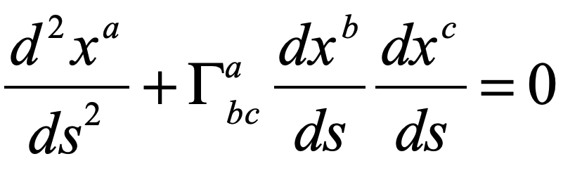
         This blog picks up where my last blog left off, having there defined the geodesic equation and presenting the Schwarzschild metric.  With those two equations in hand, we could simply solve for the null geodesics (a null geodesic is the path of a light beam through a manifold).  But there turns out to be a simpler approach that Einstein came up with himself (he never did like doing things the hard way).  He just had to sacrifice the fundamental postulate that he used to explain everything about Special Relativity.

Throwing Special Relativity Under the Bus

The fundamental postulate of Special Relativity states that the speed of light is the same for all observers.  Einstein posed this postulate, then used it to derive some of the most astonishing consequences of Special Relativity—like E = mc2.  This postulate is at the rock core of his theory of relativity and can be viewed as one of the simplest “truths” of our reality—or at least of our spacetime. 

            Yet as soon as Einstein began thinking how to extend SR to a more general situation, he realized almost immediately that he would have to throw this postulate out.   While the speed of light measured locally is always equal to c, the apparent speed of light observed by a distant observer (far from the gravitating body) is modified by gravitational time dilation and length contraction.  This means that the apparent speed of light, as observed at a distance, varies as a function of position.  From this simple conclusion Einstein derived a first estimate of the deflection of light by the Sun, though he initially was off by a factor of 2.  (The full story of Einstein’s derivation of the deflection of light by the Sun and the confirmation by Eddington is in Chapter 7 of Galileo Unbound (Oxford University Press, 2018).)

The “Optics” of Gravity

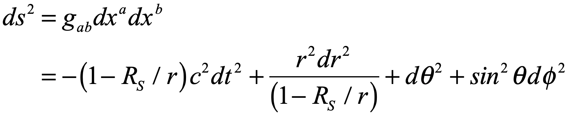
The invariant element for a light path moving radially in the Schwarzschild geometry is

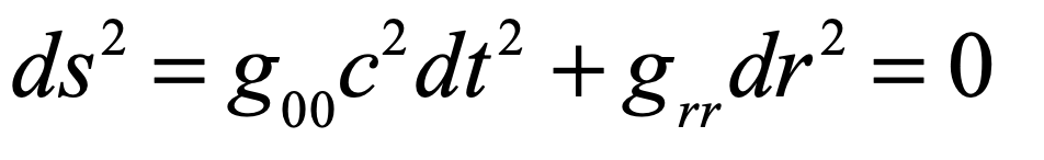
The apparent speed of light is then

where c(r) is  always less than c, when observing it from flat space.  The “refractive index” of space is defined, as for any optical material, as the ratio of the constant speed divided by the observed speed

Because the Schwarzschild metric has the property

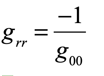
the effective refractive index of warped space-time is

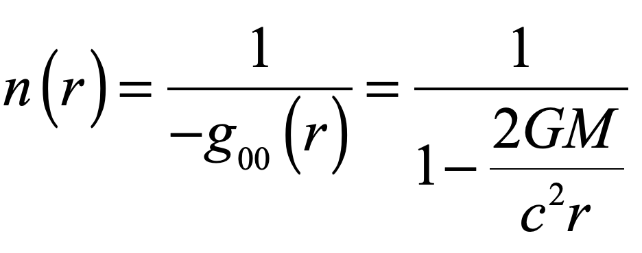
with a divergence at the Schwarzschild radius.

            The refractive index of warped space-time in the limit of weak gravity can be used in the ray equation (also known as the Eikonal equation described in an earlier blog)

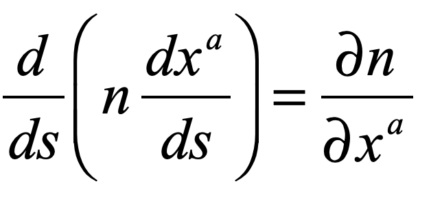
where the gradient of the refractive index of space is

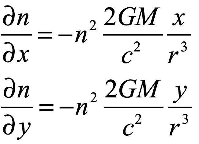
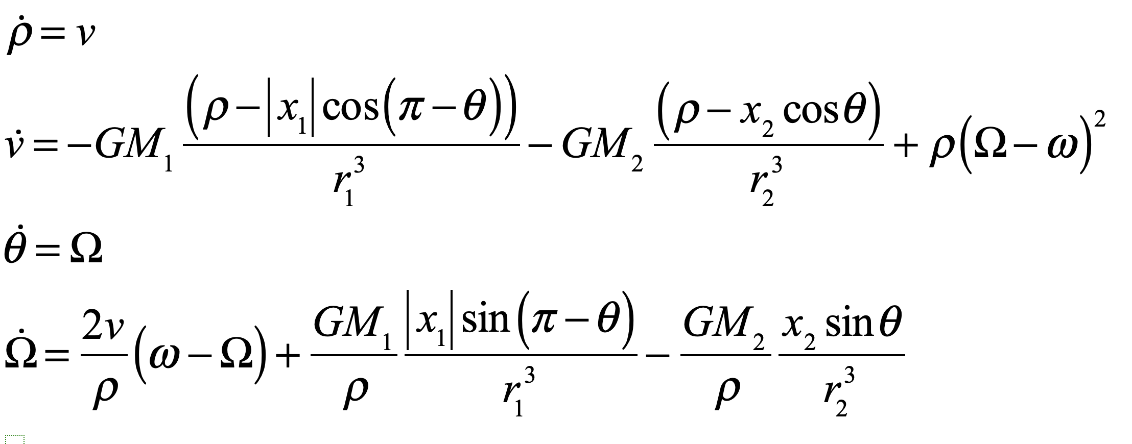
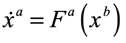
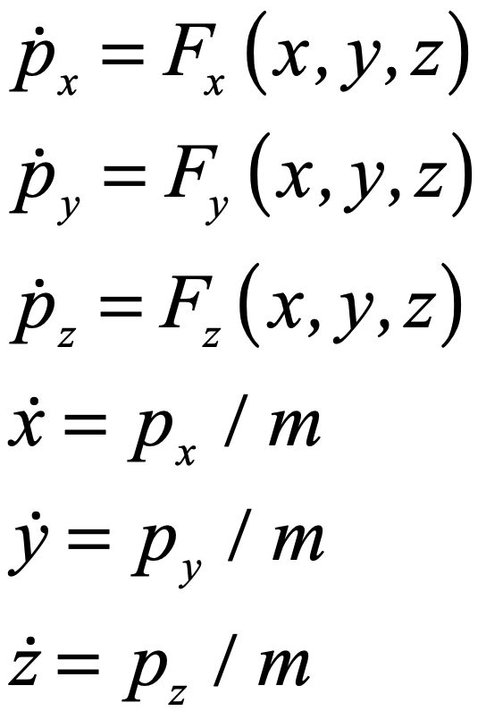
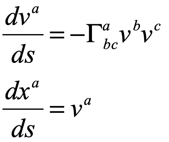
The ray equation is then a four-variable flow

These equations represent a 4-dimensional flow for a light ray confined to a plane.  The trajectory of any light path is found by using an ODE solver subject to the initial conditions for the direction of the light ray.  This is simple for us to do today with Python or Matlab, but it was also that could be done long before the advent of computers by early theorists of relativity like Max von Laue  (1879 – 1960).

The Relativity of Max von Laue

In the Fall of 1905 in Berlin, a young German physicist by the name of Max Laue was sitting in the physics colloquium at the University listening to another Max, his doctoral supervisor Max Planck, deliver a seminar on Einstein’s new theory of relativity.  Laue was struck by the simplicity of the theory, in this sense “simplistic” and hence hard to believe, but the beauty of the theory stuck with him, and he began to think through the consequences for experiments like the Fizeau experiment on partial ether drag.

         Armand Hippolyte Louis Fizeau (1819 – 1896) in 1851 built one of the world’s first optical interferometers and used it to measure the speed of light inside moving fluids.  At that time the speed of light was believed to be a property of the luminiferous ether, and there were several opposing theories on how light would travel inside moving matter.  One theory would have the ether fully stationary, unaffected by moving matter, and hence the speed of light would be unaffected by motion.  An opposite theory would have the ether fully entrained by matter and hence the speed of light in moving matter would be a simple sum of speeds.  A middle theory considered that only part of the ether was dragged along with the moving matter.  This was Fresnel’s partial ether drag hypothesis that he had arrived at to explain why his friend Francois Arago had not observed any contribution to stellar aberration from the motion of the Earth through the ether.  When Fizeau performed his experiment, the results agreed closely with Fresnel’s drag coefficient, which seemed to settle the matter.  Yet when Michelson and Morley performed their experiments of 1887, there was no evidence for partial drag.

         Even after the exposition by Einstein on relativity in 1905, the disagreement of the Michelson-Morley results with Fizeau’s results was not fully reconciled until Laue showed in 1907 that the velocity addition theorem of relativity gave complete agreement with the Fizeau experiment.  The velocity observed in the lab frame is found using the velocity addition theorem of special relativity. For the Fizeau experiment, water with a refractive index of n is moving with a speed v and hence the speed in the lab frame is

The difference in the speed of light between the stationary and the moving water is the difference

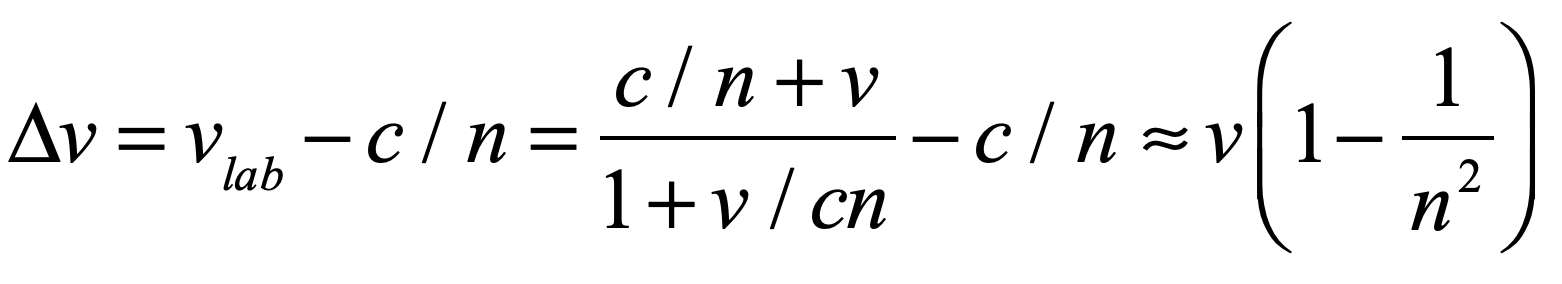
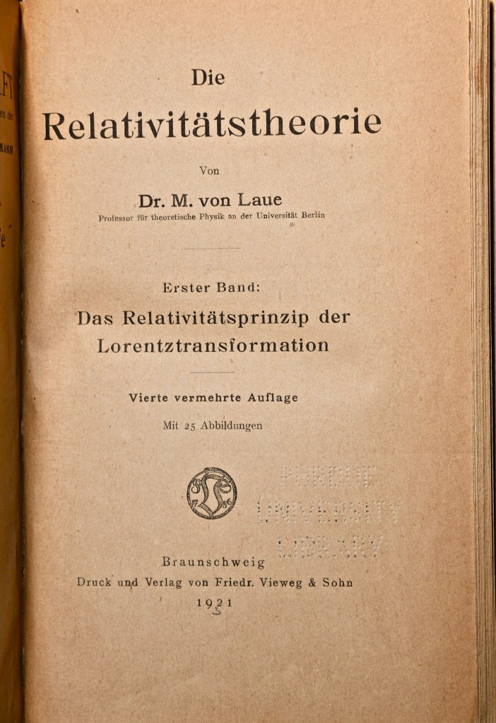
where the last term is precisely the Fresnel drag coefficient.  This was one of the first definitive “proofs” of the validity of Einstein’s theory of relativity, and it made Laue one of relativity’s staunchest proponents.  Spurred on by his success with the Fresnel drag coefficient explanation, Laue wrote the first monograph on relativity theory, publishing it in 1910. 

Fig. 1 Front page of von Laue’s textbook, first published in 1910, on Special Relativity (this is a 4-th edition published in 1921).

A Nobel Prize for Crystal X-ray Diffraction

In 1909 Laue became a Privatdozent under Arnold Sommerfeld (1868 – 1951) at the university in Munich.  In the Spring of 1912 he was walking in the Englischer Garten on the northern edge of the city talking with Paul Ewald (1888 – 1985) who was finishing his doctorate with Sommerfed studying the structure of crystals.  Ewald was considering the interaction of optical wavelength with the periodic lattice when it struck Laue that x-rays would have the kind of short wavelengths that would allow the crystal to act as a diffraction grating to produce multiple diffraction orders.  Within a few weeks of that discussion, two of Sommerfeld’s students (Friedrich and Knipping) used an x-ray source and photographic film to look for the predicted diffraction spots from a copper sulfate crystal.  When the film was developed, it showed a constellation of dark spots for each of the diffraction orders of the x-rays scattered from the multiple periodicities of the crystal lattice.  Two years later, in 1914, Laue was awarded the Nobel prize in physics for the discovery.  That same year his father was elevated to the hereditary nobility in the Prussian empire and Max Laue became Max von Laue.

            Von Laue was not one to take risks, and he remained conservative in many of his interests.  He was immensely respected and played important roles in the administration of German science, but his scientific contributions after receiving the Nobel Prize were only modest.  Yet as the Nazis came to power in the early 1930’s, he was one of the few physicists to stand up and resist the Nazi take-over of German physics.  He was especially disturbed by the plight of the Jewish physicists.  In 1933 he was invited to give the keynote address at the conference of the German Physical Society in Wurzburg where he spoke out against the Nazi rejection of relativity as they branded it “Jewish science”.  In his speech he likened Einstein, the target of much of the propaganda, to Galileo.  He said, “No matter how great the repression, the representative of science can stand erect in the triumphant certainty that is expressed in the simple phrase: And yet it moves.”  Von Laue believed that truth would hold out in the face of the proscription against relativity theory by the Nazi regime.  The quote “And yet it moves” is supposed to have been muttered by Galileo just after his abjuration before the Inquisition, referring to the Earth moving around the Sun.  Although the quote is famous, it is believed to be a myth.

            In an odd side-note of history, von Laue sent his gold Nobel prize medal to Denmark for its safe keeping with Niels Bohr so that it would not be paraded about by the Nazi regime.  Yet when the Nazis invaded Denmark, to avoid having the medals fall into the hands of the Nazis, the medal was dissolved in aqua regia by a member of Bohr’s team, George de Hevesy.  The gold completely dissolved into an orange liquid that was stored in a beaker high on a shelf through the war.  When Denmark was finally freed, the dissolved gold was precipitated out and a new medal was struck by the Nobel committee and re-presented to von Laue in a ceremony in 1951. 

The Orbits of Light Rays

Von Laue’s interests always stayed close to the properties of light and electromagnetic radiation ever since he was introduced to the field when he studied with Woldemor Voigt at Göttingen in 1899.  This interest included the theory of relativity, and only a few years after Einstein published his theory of General Relativity and Gravitation, von Laue added to his earlier textbook on relativity by writing a second volume on the general theory.  The new volume was published in 1920 and included the theory of the deflection of light by gravity. 

         One of the very few illustrations in his second volume is of light coming into interaction with a super massive gravitational field characterized by a Schwarzschild radius.  (No one at the time called it a “black hole”, nor even mentioned Schwarzschild.  That terminology came much later.)  He shows in the drawing, how light, if incident at just the right impact parameter, would actually loop around the object.  This is the first time such a diagram appeared in print, showing the trajectory of light so strongly affected by gravity.

Fig. 2 A page from von Laue’s second volume on relativity (first published in 1920) showing the orbit of a photon around a compact mass with “gravitational cutoff” (later known as a “black hole:”). The figure is drawn semi-quantitatively, but the phenomenon was clearly understood by von Laue.

Python Code: gravlens.py

#!/usr/bin/env python3
# -*- coding: utf-8 -*-
"""
gravlens.py
Created on Tue May 28 11:50:24 2019
@author: nolte
D. D. Nolte, Introduction to Modern Dynamics: Chaos, Networks, Space and Time, 2nd ed. (Oxford,2019)
"""

import numpy as np
import matplotlib as mpl
from mpl_toolkits.mplot3d import Axes3D
from scipy import integrate
from matplotlib import pyplot as plt
from matplotlib import cm
import time
import os

plt.close('all')

def create_circle():
	circle = plt.Circle((0,0), radius= 10, color = 'black')
	return circle

def show_shape(patch):
	ax=plt.gca()
	ax.add_patch(patch)
	plt.axis('scaled')
	plt.show()
    
def refindex(x,y):
    
    A = 10
    eps = 1e-6
    
    rp0 = np.sqrt(x**2 + y**2);
        
    n = 1/(1 - A/(rp0+eps))
    fac = np.abs((1-9*(A/rp0)**2/8))   # approx correction to Eikonal
    nx = -fac*n**2*A*x/(rp0+eps)**3
    ny = -fac*n**2*A*y/(rp0+eps)**3
     
    return [n,nx,ny]

def flow_deriv(x_y_z,tspan):
    x, y, z, w = x_y_z
    
    [n,nx,ny] = refindex(x,y)
        
    yp = np.zeros(shape=(4,))
    yp[0] = z/n
    yp[1] = w/n
    yp[2] = nx
    yp[3] = ny
    
    return yp
                
for loop in range(-5,30):
    
    xstart = -100
    ystart = -2.245 + 4*loop
    print(ystart)
    
    [n,nx,ny] = refindex(xstart,ystart)


    y0 = [xstart, ystart, n, 0]

    tspan = np.linspace(1,400,2000)

    y = integrate.odeint(flow_deriv, y0, tspan)

    xx = y[1:2000,0]
    yy = y[1:2000,1]


    plt.figure(1)
    lines = plt.plot(xx,yy)
    plt.setp(lines, linewidth=1)
    plt.show()
    plt.title('Photon Orbits')
    
c = create_circle()
show_shape(c)
axes = plt.gca()
axes.set_xlim([-100,100])
axes.set_ylim([-100,100])

# Now set up a circular photon orbit
xstart = 0
ystart = 15

[n,nx,ny] = refindex(xstart,ystart)

y0 = [xstart, ystart, n, 0]

tspan = np.linspace(1,94,1000)

y = integrate.odeint(flow_deriv, y0, tspan)

xx = y[1:1000,0]
yy = y[1:1000,1]

plt.figure(1)
lines = plt.plot(xx,yy)
plt.setp(lines, linewidth=2, color = 'black')
plt.show()

One of the most striking effects of gravity on photon trajectories is the possibility for a photon to orbit a black hole in a circular orbit. This is shown in Fig. 3 as the black circular ring for a photon at a radius equal to 1.5 times the Schwarzschild radius. This radius defines what is known as the photon sphere. However, the orbit is not stable. Slight deviations will send the photon spiraling outward or inward.

The Eikonal approximation does not strictly hold under strong gravity, but the Eikonal equations with the effective refractive index of space still yield semi-quantitative behavior. In the Python code, a correction factor is used to match the theory to the circular photon orbits, while still agreeing with trajectories far from the black hole. The results of the calculation are shown in Fig. 3. For large impact parameters, the rays are deflected through a finite angle. At a critical impact parameter, near 3 times the Schwarzschild radius, the ray loops around the black hole. For smaller impact parameters, the rays are captured by the black hole.

Fig. 3 Photon orbits near a black hole calculated using the Eikonal equation and the effective refractive index of warped space. One ray, near the critical impact parameter, loops around the black hole as predicted by von Laue. The central black circle is the black hole with a Schwarzschild radius of 10 units. The black ring is the circular photon orbit at a radius 1.5 times the Schwarzschild radius.

Photons pile up around the black hole at the photon sphere. The first image ever of the photon sphere of a black hole was made earlier this year (announced April 10, 2019). The image shows the shadow of the supermassive black hole in the center of Messier 87 (M87), an elliptical galaxy 55 million light-years from Earth. This black hole is 6.5 billion times the mass of the Sun. Imaging the photosphere required eight ground-based radio telescopes placed around the globe, operating together to form a single telescope with an optical aperture the size of our planet.  The resolution of such a large telescope would allow one to image a half-dollar coin on the surface of the Moon, although this telescope operates in the radio frequency range rather than the optical.

Fig. 4 Scientists have obtained the first image of a black hole, using Event Horizon Telescope observations of the center of the galaxy M87. The image shows a bright ring formed as light bends in the intense gravity around a black hole that is 6.5 billion times more massive than the Sun.

By David D. Nolte, July 29, 2019

Further Reading

Introduction to Modern Dynamics: Chaos, Networks, Space and Time, 2nd Ed. (Oxford University Press, 2019)

Interference: The History of Optical Interferometry and the Scientists who Tamed Light (Oxford University Press, 2023)

B. Lavenda, The Optical Properties of Gravity, J. Mod. Phys, 8 8-3-838 (2017)


New from Oxford University Press: Interference and the History of Light and Optics (2023)

Getting Armstrong, Aldrin and Collins Home from the Moon: Apollo 11 and the Three-Body Problem

Fifty years ago on the 20th of July at nearly 11 o’clock at night, my brothers and I were peering through the screen door of a very small 1960’s Shasta compact car trailer watching the TV set on the picnic table outside the trailer door.  Our family was at a camp ground in southern Michigan and the mosquitos were fierce (hence why we were inside the trailer looking out through the screen).  Neil Armstrong was about to be the first human to step foot on the Moon.  The image on the TV was a fuzzy black and white, with barely recognizable shapes clouded even more by the dirt and dead bugs on the screen, but it is a memory etched in my mind.  I was 10 years old and I was convinced that when I grew up I would visit the Moon myself, because by then Moon travel would be like flying to Europe.  It didn’t turn out that way, and fifty years later it’s a struggle to even get back there. 

The dangers could have become life-threatening for the crew of Apollo 11. If they miscalculated their trajectory home and had bounced off the Earth’s atmosphere, they would have become a tragic demonstration of the chaos of three-body orbits.

So maybe I won’t get to the Moon, but maybe my grandchildren will.  And if they do, I hope they know something about the three-body problem in physics, because getting to and from the Moon isn’t as easy as it sounds.  Apollo 11 faced real danger at several critical points on its flight plan, but all went perfectly (except overshooting their landing site and that last boulder field right before Armstrong landed). Some of those dangers became life-threatening for the crew of Apollo 13, and if they had miscalculated their trajectory home and had bounced off the Earth’s atmosphere, they would have become a tragic demonstration of the chaos of three-body orbits.  In fact, their lifeless spaceship might have returned to the Moon and back to Earth over and over again, caught in an infinite chaotic web.

The complexities of trajectories in the three-body problem arise because there are too few constants of motion and too many degrees of freedom.  To get an intuitive picture of how the trajectory behaves, it is best to start with a problem known as the restricted three-body problem.

The Saturn V Booster, perhaps the pinnacle of “muscle and grit” space exploration.

The Restricted Three-Body Problem

The restricted three-body problem was first considered by Leonhard Euler in 1762 (for a further discussion of the history of the three-body problem, see my Blog from July 5).  For the special case of circular orbits of constant angular frequency, the motion of the third mass is described by the Lagrangian

where the potential is time dependent because of the motion of the two larger masses.  Lagrange approached the problem by adopting a rotating reference frame in which the two larger masses m1 and m2 move along the stationary line defined by their centers.  The new angle variable is theta-prime.  The Lagrangian in the rotating frame is

where the effective potential is now time independent.  The first term in the effective potential is the Coriolis effect and the second is the centrifugal term.  The dynamical flow in the plane is four dimensional, and the four-dimensional flow is

where the position vectors are in the center-of-mass frame

relative to the positions of the Earth and Moon (x1 and x2) in the rotating frame in which they are at rest along the x-axis.

A single trajectory solved for this flow is shown in Fig. 1 for a tiny object passing back and forth chaotically between the Earth and the Moon. The object is considered to be massless, or at least so small it does not perturb the Earth-Moon system. The energy of the object was selected to allow it to pass over the potential barrier of the Lagrange-Point L1 between the Earth and the Moon. The object spends most of its time around the Earth, but now and then will get into a transfer orbit that brings it around the Moon. This would have been the fate of Apollo 11 if their last thruster burn had failed.

Fig. 1 The trajectory of a tiny object in the planar three-body problem interacting with a large mass (Earth on the left) and a small mass (Moon on the right). The energy of the trajectory allows it to pass back and forth chaotically between proximity to the Earth and proximity to the Moon. The time-duration of the simulation is approximately one decade. The envelope of the trajectories is called the “Hill region” named after one of the the first US astrophysicists George William Hill (1838-1914) who studied the 3-body problem of the Moon.

Contrast the orbit of Fig. 1 with the simple flight plan of Apollo 11 on the banner figure. The chaotic character of the three-body problem emerges for a “random” initial condition. You can play with different initial conditions in the following Python code to explore the properties of this dynamical problem. Note that in this simulation, the mass of the Moon was chosen about 8 times larger than in nature to exaggerate the effect of the Moon.

Python Code: Hill.py

(Python code on GitHub.)

#!/usr/bin/env python3
# -*- coding: utf-8 -*-
"""
Hill.py
Created on Tue May 28 11:50:24 2019
@author: nolte
D. D. Nolte, Introduction to Modern Dynamics: Chaos, Networks, Space and Time, 2nd ed. (Oxford,2019)
"""

import numpy as np
import matplotlib as mpl
from mpl_toolkits.mplot3d import Axes3D
from scipy import integrate
from matplotlib import pyplot as plt
from matplotlib import cm
import time
import os

plt.close('all')

womega = 1
R = 1
eps = 1e-6

M1 = 1     % Mass of the Earth
M2 = 1/10     % Mass of the Moon
chsi = M2/M1

x1 = -M2*R/(M1+M2)    % Earth location in rotating frame
x2 = x1 + R     % Moon location

def poten(y,c):
    
    rp0 = np.sqrt(y**2 + c**2);
    thetap0 = np.arctan(y/c);
        
    rp1 = np.sqrt(x1**2 + rp0**2 - 2*np.abs(rp0*x1)*np.cos(np.pi-thetap0));
    rp2 = np.sqrt(x2**2 + rp0**2 - 2*np.abs(rp0*x2)*np.cos(thetap0));
    V = -M1/rp1 -M2/rp2 - E;
     
    return [V]

def flow_deriv(x_y_z,tspan):
    x, y, z, w = x_y_z
    
    r1 = np.sqrt(x1**2 + x**2 - 2*np.abs(x*x1)*np.cos(np.pi-z));
    r2 = np.sqrt(x2**2 + x**2 - 2*np.abs(x*x2)*np.cos(z));
        
    yp = np.zeros(shape=(4,))
    yp[0] = y
    yp[1] = -womega**2*R**3*(np.abs(x)-np.abs(x1)*np.cos(np.pi-z))/(r1**3+eps) - womega**2*R**3*chsi*(np.abs(x)-abs(x2)*np.cos(z))/(r2**3+eps) + x*(w-womega)**2
    yp[2] = w
    yp[3] = 2*y*(womega-w)/x - womega**2*R**3*chsi*abs(x2)*np.sin(z)/(x*(r2**3+eps)) + womega**2*R**3*np.abs(x1)*np.sin(np.pi-z)/(x*(r1**3+eps))
    
    return yp
                
r0 = 0.64   % initial radius
v0 = 0.3    % initial radial speed
theta0 = 0   % initial angle
vrfrac = 1   % fraction of speed in radial versus angular directions

rp1 = np.sqrt(x1**2 + r0**2 - 2*np.abs(r0*x1)*np.cos(np.pi-theta0))
rp2 = np.sqrt(x2**2 + r0**2 - 2*np.abs(r0*x2)*np.cos(theta0))
V = -M1/rp1 - M2/rp2
T = 0.5*v0**2
E = T + V

vr = vrfrac*v0
W = (2*T - v0**2)/r0

y0 = [r0, vr, theta0, W]   % This is where you set the initial conditions

tspan = np.linspace(1,2000,20000)

y = integrate.odeint(flow_deriv, y0, tspan)

xx = y[1:20000,0]*np.cos(y[1:20000,2]);
yy = y[1:20000,0]*np.sin(y[1:20000,2]);

plt.figure(1)
lines = plt.plot(xx,yy)
plt.setp(lines, linewidth=0.5)
plt.show()

In the code, set the position and speed of the Apollo command module on lines 56-59 and put in the initial conditions on line 70. The mass of the Moon in nature is 1/81 of the mass of the Earth, which shrinks the L1 “bottleneck” to a much smaller region that you can explore to see what the fate of the Apollo missions could have been.

Further Reading

The Three-body Problem, Longitude at Sea, and Lagrange’s Points

Introduction to Modern Dynamics: Chaos, Networks, Space and Time, 2nd Ed. (Oxford University Press, 2019)

How to Teach General Relativity to Undergraduate Physics Majors

As a graduate student in physics at Berkeley in the 1980’s, I took General Relativity (aka GR), from Bruno Zumino, who was a world-famous physicist known as one of the originators of super-symmetry in quantum gravity (not to be confused with super-asymmetry of Cooper-Fowler Big Bang Theory fame).  The class textbook was Gravitation and cosmology: principles and applications of the general theory of relativity, by Steven Weinberg, another world-famous physicist, in this case known for grand unification of the electro-weak force with electromagnetism.  With so much expertise at hand, how could I fail but to absorb the simple essence of general relativity? 

The answer is that I failed miserably.  Somehow, I managed to pass the course, but I walked away with nothing!  And it bugged me for years.  What was so hard about GR?  It took me almost a decade teaching undergraduate physics classes at Purdue in the 90’s before I realized that it my biggest obstacle had been language:  I kept mistaking the words and terms of GR as if they were English.  Words like “general covariance” and “contravariant” and “contraction” and “covariant derivative”.  They sounded like English, with lots of “co” prefixes that were hard to keep straight, but they actually are part of a very different language that I call Physics-ese

Physics-ese is a language that has lots of words that sound like English, and so you think you know what the words mean, but the words have sometimes opposite meanings than what you would guess.  And the meanings of Physics-ese are precisely defined, and not something that can be left to interpretation.  I learned this while teaching the intro courses to non-majors, because so many times when the students were confused, it turned out that it was because they had mistaken a textbook jargon term to be English.  If you told them that the word wasn’t English, but just a token standing for a well-defined object or process, it would unshackle them from their misconceptions.

Then, in the early 00’s when I started to explore the physics of generalized trajectories related to some of my own research interests, I realized that the primary obstacle to my learning anything in the Gravitation course was Physics-ese.   So this raised the question in my mind: what would it take to teach GR to undergraduate physics majors in a relatively painless manner?  This is my answer. 

More on this topic can be found in Chapter 11 of the textbook IMD2: Introduction to Modern Dynamics, 2nd Edition, Oxford University Press, 2019

Trajectories as Flows

One of the culprits for my mind block learning GR was Newton himself.  His ubiquitous second law, taught as F = ma, is surprisingly misleading if one wants to have a more general understanding of what a trajectory is.  This is particularly the case for light paths, which can be bent by gravity, yet clearly cannot have any forces acting on them. 

The way to fix this is subtle yet simple.  First, express Newton’s second law as

which is actually closer to the way that Newton expressed the law in his Principia.  In three dimensions for a single particle, these equations represent a 6-dimensional dynamical space called phase space: three coordinate dimensions and three momentum dimensions.  Then generalize the vector quantities, like the position vector, to be expressed as xa for the six dynamics variables: x, y, z, px, py, and pz

Now, as part of Physics-ese, putting the index as a superscript instead as a subscript turns out to be a useful notation when working in higher-dimensional spaces.  This superscript is called a “contravariant index” which sounds like English but is uninterpretable without a Physics-ese-to-English dictionary.  All “contravariant index” means is “column vector component”.  In other words, xa is just the position vector expressed as a column vector

This superscripted index is called a “contravariant” index, but seriously dude, just forget that “contravariant” word from Physics-ese and just think “index”.  You already know it’s a column vector.

Then Newton’s second law becomes

where the index a runs from 1 to 6, and the function Fa is a vector function of the dynamic variables.  To spell it out, this is

so it’s a lot easier to write it in the one-line form with the index notation. 

The simple index notation equation is in the standard form for what is called, in Physics-ese, a “mathematical flow”.  It is an ODE that can be solved for any set of initial conditions for a given trajectory.  Or a whole field of solutions can be considered in a phase-space portrait that looks like the flow lines of hydrodynamics.  The phase-space portrait captures the essential physics of the system, whether it is a rock thrown off a cliff, or a photon orbiting a black hole.  But to get to that second problem, it is necessary to look deeper into the way that space is described by any set of coordinates, especially if those coordinates are changing from location to location.

What’s so Fictitious about Fictitious Forces?

Freshmen physics students are routinely admonished for talking about “centrifugal” forces (rather than centripetal) when describing circular motion, usually with the statement that centrifugal forces are fictitious—only appearing to be forces when the observer is in the rotating frame.  The same is said for the Coriolis force.  Yet for being such a “fictitious” force, the Coriolis effect is what drives hurricanes and the colossal devastation they cause.  Try telling a hurricane victim that they were wiped out by a fictitious force!  Looking closer at the Coriolis force is a good way of understanding how taking derivatives of vectors leads to effects often called “fictitious”, yet it opens the door on some of the simpler techniques in the topic of differential geometry.

To start, consider a vector in a uniformly rotating frame.  Such a frame is called “non-inertial” because of the angular acceleration associated with the uniform rotation.  For an observer in the rotating frame, vectors are attached to the frame, like pinning them down to the coordinate axes, but the axes themselves are changing in time (when viewed by an external observer in a fixed frame).  If the primed frame is the external fixed frame, then a position in the rotating frame is

where R is the position vector of the origin of the rotating frame and r is the position in the rotating frame relative to the origin.  The funny notation on the last term is called in Physics-ese a “contraction”, but it is just a simple inner product, or dot product, between the components of the position vector and the basis vectors.  A basis vector is like the old-fashioned i, j, k of vector calculus indicating unit basis vectors pointing along the x, y and z axes.  The format with one index up and one down in the product means to do a summation.  This is known as the Einstein summation convention, so it’s just

Taking the time derivative of the position vector gives

and by the chain rule this must be

where the last term has a time derivative of a basis vector.  This is non-zero because in the rotating frame the basis vector is changing orientation in time.  This term is non-inertial and can be shown fairly easily (see IMD2 Chapter 1) to be

which is where the centrifugal force comes from.  This shows how a so-called fictitious force arises from a derivative of a basis vector.  The fascinating point of this is that in GR, the force of gravity arises in almost the same way, making it tempting to call gravity a fictitious force, despite the fact that it can kill you if you fall out a window.  The question is, how does gravity arise from simple derivatives of basis vectors?

The Geodesic Equation

To teach GR to undergraduates, you cannot expect them to have taken a course in differential geometry, because most of them just don’t have the time in their schedule to take such an advanced mathematics course.  In addition, there is far more taught in differential geometry than is needed to make progress in GR.  So the simple approach is to teach what they need to understand GR with as little differential geometry as possible, expressed with clear English-to-Physics-ese translations. 

For example, consider the partial derivative of a vector expressed in index notation as

Taking the partial derivative, using the always-necessary chain rule, is

where the second term is just like the extra time-derivative term that showed up in the derivation of the Coriolis force.  The basis vector of a general coordinate system may change size and orientation as a function of position, so this derivative is not in general zero.  Because the derivative of a basis vector is so central to the ideas of GR, they are given their own symbol.  It is

where the new “Gamma” symbol is called a Christoffel symbol.  It has lots of indexes, both up and down, which looks daunting, but it can be interpreted as the beta-th derivative of the alpha-th component of the mu-th basis vector.  The partial derivative is now

For those of you who noticed that some of the indexes flipped from alpha to mu and vice versa, you’re right!  Swapping repeated indexes in these “contractions” is allowed and helps make derivations a lot easier, which is probably why Einstein invented this notation in the first place.

The last step in taking a partial derivative of a vector is to isolate a single vector component Va as

where a new symbol, the del-operator has been introduced.  This del-operator is known as the “covariant derivative” of the vector component.  Again, forget the “covariant” part and just think “gradient”.  Namely, taking the gradient of a vector in general includes changes in the vector component as well as changes in the basis vector.

Now that you know how to take the partial derivative of a vector using Christoffel symbols, you are ready to generate the central equation of General Relativity:  The geodesic equation. 

Everyone knows that a geodesic is the shortest path between two points, like a great circle route on the globe.  But it also turns out to be the straightest path, which can be derived using an idea known as “parallel transport”.  To start, consider transporting a vector along a curve in a flat metric.  The equation describing this process is

Because the Christoffel symbols are zero in a flat space, the covariant derivative and the partial derivative are equal, giving

If the vector is transported parallel to itself, then there is no change in V along the curve, so that

Finally, recognizing

and substituting this in gives

This is the geodesic equation! 

Fig. 1 The geodesic equation of motion is for force-free motion through a metric space. The curvature of the trajectory is analogous to acceleration, and the generalized gradient is analogous to a force. The geodesic equation is the “F = ma” of GR.

Putting this in the standard form of a flow gives the geodesic flow equations

The flow defines an ordinary differential equation that defines a curve that carries its own tangent vector onto itself.  The curve is parameterized by a parameter s that can be identified with path length.  It is the central equation of GR, because it describes how an object follows a force-free trajectory, like free fall, in any general coordinate system.  It can be applied to simple problems like the Coriolis effect, or it can be applied to seemingly difficult problems, like the trajectory of a light path past a black hole.

The Metric Connection

Arriving at the geodesic equation is a major accomplishment, and you have done it in just a few pages of this blog.  But there is still an important missing piece before we are doing General Relativity of gravitation.  We need to connect the Christoffel symbol in the geodesic equation to the warping of space-time around a gravitating object. 

The warping of space-time by matter and energy is another central piece of GR and is often the central focus of a graduate-level course on the subject.  This part of GR does have its challenges leading up to Einstein’s Field Equations that explain how matter makes space bend.  But at an undergraduate level, it is sufficient to just describe the bent coordinates as a starting point, then use the geodesic equation to solve for so many of the cool effects of black holes.

So, stating the way that matter bends space-time is as simple as writing down the length element for the Schwarzschild metric of a spherical gravitating mass as

where RS = GM/c2 is the Schwarzschild radius.  (The connection between the metric tensor gab and the Christoffel symbol can be found in Chapter 11 of IMD2.)  It takes only a little work to find that

This means that if we have the Schwarzschild metric, all we have to do is take first partial derivatives and we will arrive at the Christoffel symbols that go into the geodesic equation.  Solving for any type of force-free trajectory is then just a matter of solving ODEs with initial conditions (performed routinely with numerical ODE solvers in Python, Matlab, Mathematica, etc.).

The first problem we will tackle using the geodesic equation is the deflection of light by gravity.  This is the quintessential problem of GR because there cannot be any gravitational force on a photon, yet the path of the photon surely must bend in the presence of gravity.  This is possible through the geodesic motion of the photon through warped space time.  I’ll take up this problem in my next Blog.


This Blog Post is a Companion to the undergraduate physics textbook Modern Dynamics: Chaos, Networks, Space and Time, 2nd ed. (Oxford, 2019) introducing Lagrangians and Hamiltonians, chaos theory, complex systems, synchronization, neural networks, econophysics and Special and General Relativity.

The Three-Body Problem, Longitude at Sea, and Lagrange’s Points

When Newton developed his theory of universal gravitation, the first problem he tackled was Kepler’s elliptical orbits of the planets around the sun, and he succeeded beyond compare.  The second problem he tackled was of more practical importance than the tracks of distant planets, namely the path of the Earth’s own moon, and he was never satisfied. 

Newton’s Principia and the Problem of Longitude

Measuring the precise location of the moon at very exact times against the backdrop of the celestial sphere was a method for ships at sea to find their longitude.  Yet the moon’s orbit around the Earth is irregular, and Newton recognized that because gravity was universal, every planet exerted a force on each other, and the moon was being tugged upon by the sun as well as by the Earth.

Newton’s attempt with the Moon was his last significant scientific endeavor

            In Propositions 65 and 66 of Book 1 of the Principia, Newton applied his new theory to attempt to pin down the moon’s trajectory, but was thwarted by the complexity of the three bodies of the Earth-Moon-Sun system.  For instance, the force of the sun on the moon is greater than the force of the Earth on the moon, which raised the question of why the moon continued to circle the Earth rather than being pulled away to the sun. Newton correctly recognized that it was the Earth-moon system that was in orbit around the sun, and hence the sun caused only a perturbation on the Moon’s orbit around the Earth.  However, because the Moon’s orbit is approximately elliptical, the Sun’s pull on the Moon is not constant as it swings around in its orbit, and Newton only succeeded in making estimates of the perturbation. 

            Unsatisfied with his results in the Principia, Newton tried again, beginning in the summer of 1694, but the problem was to too great even for him.  In 1702 he published his research, as far as he was able to take it, on the orbital trajectory of the Moon.  He could pin down the motion to within 10 arc minutes, but this was not accurate enough for reliable navigation, representing an uncertainty of over 10 kilometers at sea—error enough to run aground at night on unseen shoals.  Newton’s attempt with the Moon was his last significant scientific endeavor, and afterwards this great scientist withdrew into administrative activities and other occult interests that consumed his remaining time.

Race for the Moon

            The importance of the Moon for navigation was too pressing to ignore, and in the 1740’s a heated competition to be the first to pin down the Moon’s motion developed among three of the leading mathematicians of the day—Leonhard Euler, Jean Le Rond D’Alembert and Alexis Clairaut—who began attacking the lunar problem and each other [1].  Euler in 1736 had published the first textbook on dynamics that used the calculus, and Clairaut had recently returned from Lapland with Maupertuis.  D’Alembert, for his part, had placed dynamics on a firm physical foundation with his 1743 textbook.  Euler was first to publish with a lunar table in 1746, but there remained problems in his theory that frustrated his attempt at attaining the required level of accuracy.  

            At nearly the same time Clairaut and D’Alembert revisited Newton’s foiled lunar theory and found additional terms in the perturbation expansion that Newton had neglected.  They rushed to beat each other into print, but Clairaut was distracted by a prize competition for the most accurate lunar theory, announced by the Russian Academy of Sciences and refereed by Euler, while D’Alembert ignored the competition, certain that Euler would rule in favor of Clairaut.  Clairaut won the prize, but D’Alembert beat him into print. 

            The rivalry over the moon did not end there. Clairaut continued to improve lunar tables by combining theory and observation, while D’Alembert remained more purely theoretical.  A growing animosity between Clairaut and D’Alembert spilled out into the public eye and became a daily topic of conversation in the Paris salons.  The difference in their approaches matched the difference in their personalities, with the more flamboyant and pragmatic Clairaut disdaining the purist approach and philosophy of D’Alembert.  Clairaut succeeded in publishing improved lunar theory and tables in 1752, followed by Euler in 1753, while D’Alembert’s interests were drawn away towards his activities for Diderot’s Encyclopedia

            The battle over the Moon in the late 1740’s was carried out on the battlefield of perturbation theory.  To lowest order, the orbit of the Moon around the Earth is a Keplerian ellipse, and the effect of the Sun, though creating problems for the use of the Moon for navigation, produces only a small modification—a perturbation—of its overall motion.  Within a decade or two, the accuracy of perturbation theory calculations, combined with empirical observations, had improved to the point that accurate lunar tables had sufficient accuracy to allow ships to locate their longitude to within a kilometer at sea.  The most accurate tables were made by Tobias Mayer, who was awarded posthumously a prize of 3000 pounds by the British Parliament in 1763 for the determination of longitude at sea. Euler received 300 pounds for helping Mayer with his calculations.  This was the same prize that was coveted by the famous clockmaker John Harrison and depicted so brilliantly in Dava Sobel’s Longitude (1995).

Lagrange Points

            Several years later in 1772 Lagrange discovered an interesting special solution to the planar three-body problem with three massive points each executing an elliptic orbit around the center of mass of the system, but configured such that their positions always coincided with the vertices of an equilateral triangle [2].  He found a more important special solution in the restricted three-body problem that emerged when a massless third body was found to have two stable equilibrium points in the combined gravitational potentials of two massive bodies.  These two stable equilibrium points  are known as the L4 and L5 Lagrange points.  Small objects can orbit these points, and in the Sun-Jupiter system these points are occupied by the Trojan asteroids.  Similarly stable Lagrange points exist in the Earth-Moon system where space stations or satellites could be parked. 

For the special case of circular orbits of constant angular frequency w, the motion of the third mass is described by the Lagrangian

where the potential is time dependent because of the motion of the two larger masses.  Lagrange approached the problem by adopting a rotating reference frame in which the two larger masses m1 and m2 move along the stationary line defined by their centers. The Lagrangian in the rotating frame is

where the effective potential is now time independent.  The first term in the effective potential is the Coriolis effect and the second is the centrifugal term.

Fig. Effective potential for the planar three-body problem and the five Lagrange points where the gradient of the effective potential equals zero. The Lagrange points are displayed on a horizontal cross section of the potential energy shown with equipotential lines. The large circle in the center is the Sun. The smaller circle on the right is a Jupiter-like planet. The points L1, L2 and L3 are each saddle-point equilibria positions and hence unstable. The points L4 and L5 are stable points that can collect small masses that orbit these Lagrange points.

            The effective potential is shown in the figure for m3 = 10m2.  There are five locations where the gradient of the effective potential equals zero.  The point L1 is the equilibrium position between the two larger masses.  The points L2 and L3 are at positions where the centrifugal force balances the gravitational attraction to the two larger masses.  These are also the points that separate local orbits around a single mass from global orbits that orbit the two-body system. The last two Lagrange points at L4 and L5 are at one of the vertices of an equilateral triangle, with the other two vertices at the positions of the larger masses. The first three Lagrange points are saddle points.  The last two are at maxima of the effective potential.

L1, lies between Earth and the sun at about 1 million miles from Earth. L1 gets an uninterrupted view of the sun, and is currently occupied by the Solar and Heliospheric Observatory (SOHO) and the Deep Space Climate Observatory. L2 also lies a million miles from Earth, but in the opposite direction of the sun. At this point, with the Earth, moon and sun behind it, a spacecraft can get a clear view of deep space. NASA’s Wilkinson Microwave Anisotropy Probe (WMAP) is currently at this spot measuring the cosmic background radiation left over from the Big Bang. The James Webb Space Telescope will move into this region in 2021.


[1] Gutzwiller, M. C. (1998). “Moon-Earth-Sun: The oldest three-body problem.” Reviews of Modern Physics 70(2): 589-639.

[2] J.L. Lagrange Essai sur le problème des trois corps, 1772, Oeuvres tome 6